262391
132
Revision A
1018993
A
B
C
D
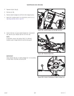
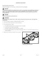
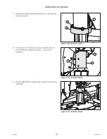
Figure 4.91: Accelerator Install
4.
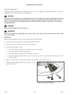
Place a wooden block between two cutterbar discs to
prevent the discs from rotating while you are tightening the
blade bolts.
IMPORTANT:
Accelerators are unidirectional: both clockwise and
counterclockwise accelerators are used on the cutterbar.
Verify the direction of the disc before installing any
accelerators. If you are unsure in which direction the
spindle rotates, refer to
4.4.5 Replacing Cutterbar Spindles,
5.
Install lock nut (A), accelerator (B), blade holder (C), and
hex-socket bolt (D). Do
NOT
tighten the hardware yet.
1004047
A
C
B
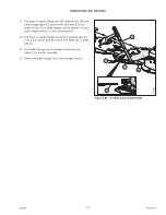
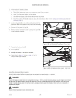
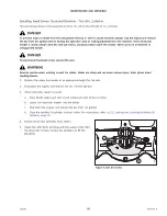
Figure 4.92: Accelerator Install
6.
Install new nut (A), flange bolt (B), and disc blade (C) onto
the disc.
1014626
A
B
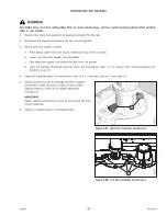
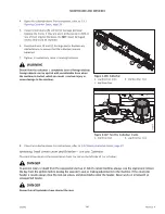
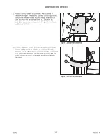
Figure 4.93: Accelerator Install
7.
Torque inside nut (A) to 58 Nm (43 lbf·ft).
8.
Torque outside nut (B) (closest to the blade) to 125 Nm
(92 lbf·ft).
9.
Repeat Steps
to
to replace the
second accelerator.
WARNING
Ensure that the cutterbar is completely clear of foreign objects.
Foreign objects can be ejected with considerable force when
the machine is started, which can result in serious injury or
cause damage to the machine.
10. Remove the wooden block.
11. Close the cutterbar doors. For instructions, refer to


