262391
20
Revision A
ϭϬϰϯϲϴϳ
A
B
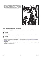
Figure 3.1: Auxiliary Lift Lock Pins
–
Left Side
4.
Retrieve the auxiliary lift lock straight pins, washers, and
Lynch pins from storage location (B) on the left side of the
carrier frame, and install the straight pins into the holes (A)
in auxiliary lift linkage on both sides of the header.
3.1.2
Removing Auxiliary Lift Locking Pins
The auxiliary lift lock pins prevent the carrier frame from moving when the header is not attached to a tractor. Auxiliary lift
lock pins must be removed before raising the header with a tractor.
DANGER
To prevent bodily injury or death from the unexpected startup of the machine, always stop the engine and remove the
key from the ignition before leaving the operator
’
s seat.
DANGER
Ensure that all bystanders have cleared the area.
1.
Connect the tractor
’
s 3-point hitch to the header. For instructions, refer to
3.7.1 Connecting the Tractor to the Rotary
IMPORTANT:
Do
NOT
raise the header when the auxiliary lift lock pins are installed. Doing so engages the hydraulic lift cylinders and
can damage the float system linkage.

