262391
136
Revision A
1003640
A
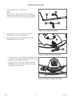
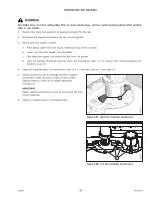
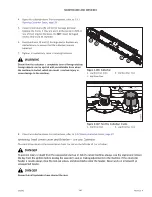
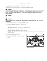
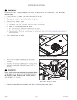
Figure 4.97: Inboard Rock Guards
4.
Guide the inboard rock guard onto the cutterbar until
tabs (A) sit on top of the cutterbar, and the bottom back
bolt holes in the rock guard line up with the holes in the
cutterbar.
1003622
A
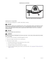
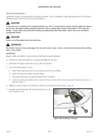
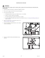
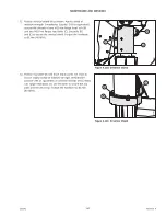
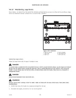
Figure 4.98: Inboard Rock Guards
5.
Install two hex head screws, washers, and lock nuts (A).
Torque the hardware to 68 Nm (50 lbf·ft).
NOTE:
Lock nuts (A) must be installed on top of the cutterbar.
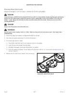
Removing Outboard Rock Guards
The outboard rock guards are secured to the cutterbar with more hardware than the inboard rock guards.
DANGER
To prevent injury or death from the unexpected start-up or fall of a raised machine, always stop the engine and remove
the key from the ignition before leaving the operator
’
s seat or making adjustments to the machine. If the rotary disc
header is raised, always close the lock-out valves, and place blocks under the header. Never work on or beneath an
unsupported header.
DANGER
Ensure that all bystanders have cleared the area.
WARNING
Exercise caution when working around the blades. Blades are sharp and can cause serious injury. Wear gloves when
handling blades.
1.
Position the rotary disc header at an appropriate height for the task.
2.
Shut down the engine, and remove the key from the ignition.


