262391
146
Revision A
1024920
A
B
C
D
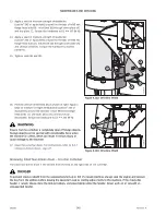
Figure 4.117: Hub Drive to Driveline Connection
6.
Lubricate spindle splines (A). For specifications, refer to the
inside back cover of this manual.
NOTE:
For clarity, the illustration shows a cutaway view of the
drum and tube shield.
7.
Insert driveline (B) at an angle and guide it past hub
drive (C) and drum (D).
8.
Insert splined spindle end (A) into the splined bore of
driveline (B).
1011137
A
A
B
C
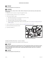
Figure 4.118: Hub Drive to Driveline Connection
9.
Place a bead of medium-strength threadlocker
(Loctite
®
243 or equivalent) around the threads of four M12
hex flange head bolts (A). Use the bolts and spacers to
secure driveline assembly (B) to hub drive (C). Torque the
bolts to 102 Nm (75 lbf·ft).
1024921
B
B
A
A
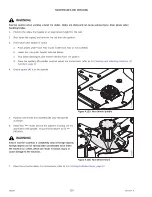
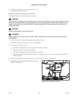
Figure 4.119: Driven Drum
10. Position two drum shields (B) as shown. Apply a bead of
medium-strength threadlocker (Loctite
®
243 or equivalent)
around the threads of eight M8 hex flange head bolts (A).
Use the bolts to secure the drum shields. Torque the
hardware to 27 Nm (239 lbf·in).


