262391
101
Revision A
3.
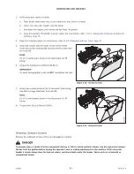
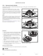
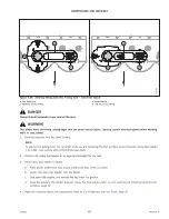
If the rotary disc header is raised:
a.
Place blocks under each end, or just inside each end, of the cutterbar.
b.
Lower the rotary disc header onto the blocks.
c.
Shut down the engine, and remove the key from the ignition.
d.
Close the auxiliary lift cylinder lock-out valves. For instructions, refer to
3.2.1 Locking and Unlocking Auxiliary Lift
.
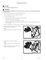
1017487
A
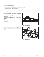
Figure 4.37: Disc Spindle
4.
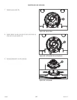
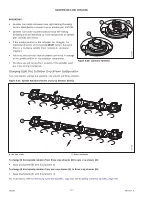
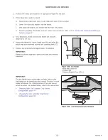
Install spacer plate (A) on the spindle.
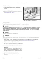
1011305
B
A
C
D
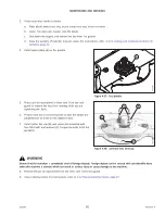
Figure 4.38: Cutterbar Disc and Cap
5.
Place a pin (or equivalent) in front hole (D) of the rock
guard to prevent the disc from rotating while you are
tightening the bolts.
6.
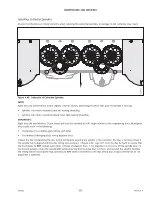
Position new disc (A) on the spindle so that the blades are
perpendicular to those on the adjacent discs.
7.
Install cutter disc cap (B), and secure the assembly with
four M12 bolts and washers (C). Torque the bolts to 85 Nm
(63 lbf·ft).
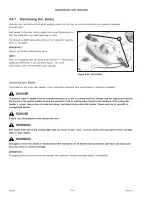
WARNING
Ensure that the cutterbar is completely clear of foreign objects. Foreign objects can be ejected with considerable force
when the machine is started, which can result in serious injury or cause damage to the machine.
8.
Remove the pin (or equivalent) from the front hole of the rock guard.
9.
Close cutterbar doors. For instructions, refer to


