215922
371
Revision A
1000542
A
B
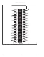
Figure 5.227: Drive Wheel Leg Jacking Point
1.
Place a jack under leg jack point (A), and raise the drive
wheel slightly off the jack stand.
2.
Remove the jack stand from under cylinder lift mount (B).
Lower the drive wheel to the ground.
3.
Remove the jack.
5.15.9
Caster Wheels
The casters wheels
’
tire pressure, wheel nut torque, and the anti-shimmy dampeners should be inspected regularly.
Setting Walking Beam Extension Limits
The walking beam extensions allow the caster wheels to retract for narrow transport or extend for normal/field operation.
The amount of extension is controlled with adjustable limit stops.
DANGER
To prevent injury or death from the unexpected start-up of the machine, always stop the engine and remove the key
from the ignition before leaving the operator
’
s seat for any reason.
1.
Ensure the narrow transport function is enabled on the Harvest Performance Tracker (HPT). For instructions, refer to
3.17.6 Enabling Narrow Transport System in the Harvest Performance Tracker, page 101
2.
Retract the walking beam extensions to the narrowest position. For instructions, refer to
.
3.
Shut down the engine, and remove the key from the ignition.
4.
Remove bolts (A) and move extension limit stops (1 per side) to desired position: 1, 2, 3, or storage position. By
installing the limit stops with center tab facing inboard or outboard, the limit stops provide 6 different position
options.
Limit stop position examples:
•
Limit stop (B) shown in storage position outside the welded stop: walking beam has maximum extension.
•
Limit stop (C) in position 3: walking beam has minimum extension (center tab shown facing inboard).
•
Limit stop (D) in position 2: walking beam in a middle position (center tab shown facing outboard).
5.
Ensure the extension limit stop positions are the same on both sides of the walking beam and reinstall using bolts (A).

