background image

5

 START-UP 

38 

OPTIWAVE 1010

www.krohne.com

10/2016 - 4003537403 - MA OPTIWAVE 1010 R03 en

5.3.5  Diagnosis window

Use this data to do a check of the device's condition (error messages etc.).

You can do one of these three procedures to open the Diagnosis window:

Open the window from the Start

Start

Start

Start window. Click on Start

Start

Start

Start in the DTM menu and then click on the 

Diagnosis

Diagnosis

Diagnosis

Diagnosis button at the bottom of the Start

Start

Start

Start window.

Open the window from the main toolbar. Click on Device > Diagnosis

Device > Diagnosis

Device > Diagnosis

Device > Diagnosis.

Open the window from the Project

Project

Project

Project window. Right click on the device (OPTIWAVE 1010

OPTIWAVE 1010

OPTIWAVE 1010

OPTIWAVE 1010) in the 

project list, then click on Diagnosis

Diagnosis

Diagnosis

Diagnosis.

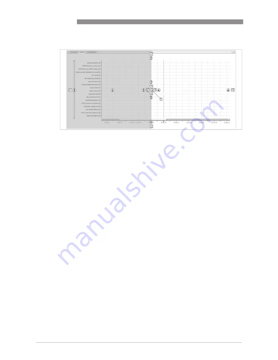
Figure 5-6: How to put two or more graphs on one tab

1  

Graph position symbol: create another tab for this graph

2  

Graph position symbol: move this graph to the top

3  

Graph position symbol: move this graph to the left side

4  

Graph position symbol: move this graph to the right side

5  

Graph position symbol: move this graph to the bottom

6  

In this example, the user clicks on the graph position symbol 

3

 and the graph is shown on the left side on the same tab

Summary of Contents for OPTIWAVE 1010

Page 1: ...ransmitter for bypass chambers and magnetic level indicators BM 26 Advanced OPTIWAVE 1010 OPTIWAVE 1010 OPTIWAVE 1010 OPTIWAVE 1010 Handbook Handbook Handbook Handbook KROHNE 10 2016 4003537403 MA OPT...

Page 2: ...any part thereof without the prior written authorisation of KROHNE Messtechnik GmbH Subject to change without notice 2 www krohne com 10 2016 4003537403 MA OPTIWAVE 1010 R03 en Copyright 2016 by KROH...

Page 3: ...e of delivery 14 2 2 Device description 14 2 3 Visual Check 15 2 4 Nameplates 16 2 4 1 Nameplate example 16 3 Installation 17 3 1 General notes on installation 17 3 2 Storage 17 3 3 Transport 18 3 4 P...

Page 4: ...4 6 4 Menu overview 46 6 5 How to change device settings 47 6 6 Data about parameters online Help 48 6 7 Device settings 49 6 7 1 Password protection for device settings 49 6 7 2 Import Export 50 6 7...

Page 5: ...79 9 3 1 Point to Point connection analogue digital mode 79 9 3 2 Multi Drop connection 2 wire connection 79 9 4 HART device variables 79 9 5 Field Communicator 475 FC 475 80 9 5 1 Installation 80 9...

Page 6: ...itter measures distance and level of liquids or the top of a float It does not touch the measured product This radar level transmitter can only be used if it is correctly installed and aligned on a by...

Page 7: ...opean Standards related to this device refer to the EU Declaration of Conformity You can find this documentation on the DVD ROM supplied with the device or it can be downloaded free of charge from the...

Page 8: ...e coated with a microwave proof coating when necessary i e electrically conductive coating manholes or connection flanges at the tank shall be closed to ensure a low level leakage of the signal into t...

Page 9: ...ly approved by KROHNE may void the FCC authorization to operate this equipment This equipment has been tested and found to comply with the limits for a Class A digital device pursuant to Part 15 of th...

Page 10: ...ice complies with Industry Canada licence exempt RSS 210 Operation is subject to the following two conditions 1 This device may not cause harmful interference and 2 This device must accept any interfe...

Page 11: ...over the Internet e g when communicating by e mail may involve gaps in security It is not possible to protect such data completely against access by third parties We hereby expressly prohibit the use...

Page 12: ...n To prevent any injury to the user or damage to the device it is essential that you read the information in this document and observe applicable national standards safety requirements and accident pr...

Page 13: ...arnings must be observed without fail Even partial disregard of this warning can lead to serious health problems and even death There is also the risk of seriously damaging the device or parts of the...

Page 14: ...e measuring principle refer to Measuring principle on page 68 INFORMATION Do a check of the packing list to make sure that you have all the elements given in the order Figure 2 1 Scope of delivery 1 D...

Page 15: ...ges or signs of rough handling Report damage to the carrier and to the local office of the manufacturer Figure 2 3 Visual check 1 Device nameplate for more data refer to Nameplate example on page 16 I...

Page 16: ...red according to your order Check for the correct supply voltage printed on the nameplate Figure 2 4 Non Ex nameplate attached to the housing 1 Cable entry size 2 Country of manufacture 3 Input output...

Page 17: ...f the packing list to make sure that you have all the elements given in the order INFORMATION Look at the device nameplate to ensure that the device is delivered according to your order Check for the...

Page 18: ...NG OPTIWAVE1010 attached to a magnetic level indicator OPTIWAVE1010 attached to a magnetic level indicator OPTIWAVE1010 attached to a magnetic level indicator OPTIWAVE1010 attached to a magnetic level...

Page 19: ...tallic grid to prevent injury Figure 3 3 Pressure and temperature ranges 1 Bypass chamber temperature Non Ex devices Depends on the device versions and the seal material Refer to the table that follow...

Page 20: ...eek without 40 100 40 212 1 16 14 5 232 Kalrez 6375 with Metapeek without 20 100 4 212 EPDM with Metapeek without 40 100 40 212 Metaglas and distance piece FKM FPM with Metaglas with 40 150 40 302 1 4...

Page 21: ...Ambient temperature process temperature in C Figure 3 4 Ambient temperature process temperature in C Ambient temperature process temperature in F Figure 3 5 Ambient temperature process temperature in...

Page 22: ...gned with the process connections of the bypass chamber Figure 3 6 Recommended mounting position 1 Internal tube diameter Min Max 38 56 mm 1 50 2 20 2 Float offset the distance between the surface of...

Page 23: ...delivery of the device obey the instructions that follow WARNING If the device uses a float to measure the level of the liquid slowly pressurize the bypass chamber A float can damage the PEEK cone of...

Page 24: ...f the device Attach the two locking nuts to the threads on the weather protection clamp Tighten the locking nuts with a 10 mm socket Part 1 How to attach the weather protection to the device Figure 3...

Page 25: ...ure For more data about the overall dimensions of the weather protection refer to Dimensions and weights on page 76 3 9 How to open the weather protection If your device has the weather protection opt...

Page 26: ...the measuring device may only be carried out by properly trained specialists INFORMATION Look at the device nameplate to ensure that the device is delivered according to your order Check for the corre...

Page 27: ...le into the opening of the cable gland Then put the electrical cable into the opening of the ferrite choke 3 Put the electrical wires in the connector terminals Tighten the terminal screws with a smal...

Page 28: ...cation 3 Optional connection to the grounding terminal 4 Output 14 5 32 VDC for an output of 22 mA at the terminal 5 Device INFORMATION Electrical polarity has no effect on device operation DANGER For...

Page 29: ...agrees with the national electrical code Make a loop of cable in front of the device 1 to prevent leakage into the housing Tighten the cable feedthrough 2 INFORMATION The device fulfils all requireme...

Page 30: ...a network with a device address from 1 to 63 The device output is factory set to communicate point to point To change the communication mode from point to point point to point point to point point to...

Page 31: ...OPTIWAVE 1010 R03 en 4 5 3 Multi drop networks Figure 4 6 Multi drop network non Ex 1 Address of the device each device must have a different address in multidrop networks 2 4 mA HART 3 Resistor for H...

Page 32: ...ure the device with A connection to a system or PC with PACTware You can download the Device Type Manager DTM file from the website It is also supplied on the DVD ROM delivered with the device A conne...

Page 33: ...the field device This standard agrees with IEC 62453 Field devices are easily integrated Installation is supported by a user friendly Wizard Figure 5 1 Start window for the DTM in PACTware 1 Status d...

Page 34: ...ata to make sure that the device operates correctly For more data refer to Simulation window on page 40 5 3 2 Software installation Equipment needed A computer One of these two solutions 1 the DVD ROM...

Page 35: ...dow Open the window from the main toolbar Click on Device Measured value Measurements Device Measured value Measurements Device Measured value Measurements Device Measured value Measurements Open the...

Page 36: ...the device was energized 3 Graph Electronics block temperature C or F against time time after the device was energized 4 Graph Current output mA against time time after the device was energized 5 Grap...

Page 37: ...ts new position INFORMATION To record data in Imperial USCS units ft F etc in the analysis window go to HART menu on the Parameters window and change the length unit to ft feet ft feet ft feet ft feet...

Page 38: ...Diagnosis Device Diagnosis Device Diagnosis Device Diagnosis Open the window from the Project Project Project Project window Right click on the device OPTIWAVE 1010 OPTIWAVE 1010 OPTIWAVE 1010 OPTIWAV...

Page 39: ...7 DTM Diagnosis screen 1 Summary status of the device since the last check Click on the list for more data about an applicable error 2 Data about the applicable error and the recommended solution 3 N...

Page 40: ...ation button at the bottom of the Start Start Start Start window Open the window from the main toolbar Click on Device Simulation Device Simulation Device Simulation Device Simulation Open the window...

Page 41: ...unication in the Device Catalog window The COMx element is added below HOST PC in the project structure Click on OK to save changes or Cancel to cancel the new configuration Double click on the OPTIWA...

Page 42: ...olbar i End of the procedure CAUTION Make sure that the settings in the DTM and the device are regularly synchronized If you do not synchronize the settings it is possible that settings in the DTM and...

Page 43: ...R03 en Right click on the OPTIWAVE 1010 element in the Project window Click on Load from device in the list i End of the procedure Procedure 3 Right click on the OPTIWAVE 1010 element in the Project w...

Page 44: ...i End of the procedure CAUTION Make sure that the settings in the DTM and the device are regularly synchronized If you do not synchronize the settings it is possible that settings in the DTM and the...

Page 45: ...R03 en Right click on the OPTIWAVE 1010 element in the Project window Click on Store to device in the list i End of the procedure Procedure 3 Right click on the OPTIWAVE 1010 element in the Project w...

Page 46: ...lication Float offset calculation Application Float offset calculation Application Float offset calculation Application Float offset calculation in the DTM menu to calculate the new float offset value...

Page 47: ...ed value If the value is too large or too small a red exclamation mark is shown adjacent to the incorrect value CAUTION If you change the device settings the DTM saves this data in the workstation It...

Page 48: ...MA OPTIWAVE 1010 R03 en 6 6 Data about parameters online Help Right click on the text for data about parameters A tooltip shows the default value data set value new value minimum value and maximum va...

Page 49: ...ure Project pane or b Right click on OPTIWAVE 1010 element in the project structure Project pane and select Parameter in the drop down list box Click on Login Logout Click on the Select action Select...

Page 50: ...ane and select Parameter in the drop down list box Click on Login Logout Click on the Select action Select action Select action Select action menu and set it to disable Supervisor password Push the Ex...

Page 51: ...data only click in the Configuration Data tick box but not the Service Data tick box If you want basic and advanced settings data click on the two tick boxes and enter the service password Click on th...

Page 52: ...en 6 7 3 Information This is a read only menu that gives data in the list that follows Firmware version Configuration changed counter Software revision Hardware revision Complete device serial number...

Page 53: ...actory but you can change it on site 2 Maximum distance 2 Maximum distance 2 Maximum distance 2 Maximum distance This is the distance from the matching element to the bottom point on the scale The end...

Page 54: ...er Distance Level Level Output range This menu item sets the limits of the electrical current range to 1 of the 2 available options standard limits 4 20 mA or NAMUR NE 43 compliant limits 3 8 20 5 mA...

Page 55: ...ange Output range in the Current output Current output Current output Current output menu The level or distance value of the start point is always zero Read only Scaling max This menu item gives the e...

Page 56: ...cesses several measurement readings to filter out disturbances Increasing the time constant will smoothen the integrated readings decreasing will roughen the reading s seconds min max 0 100 s 1 s Max...

Page 57: ...et calculation Push the button at the bottom of the window Make a selection from the float types Ti L 472 Ti L 292 or 316L L 297 Enter the density of the product in the bypass chamber Make sure that t...

Page 58: ...can also set the length unit INFORMATION If you change the length unit in the HART HART HART HART menu this will also change the length units in the Basic Basic Basic Basic Parameters Parameters Param...

Page 59: ...te interval INFORMATION Click on the button below the device status symbol to change from distance to level measurement Function Function description Selection list or range of values Default Status d...

Page 60: ...not operate correctly The fault message stays on Hardware error Microwave error Hardware error EEPROM error Config Hardware error EEPROM error HART Hardware error Output current calibration not valid...

Page 61: ...he device s hardware is defective Replace the signal converter For more data refer to Service warranty on page 63 EEPROM error HART The device s hardware is defective Replace the signal converter For...

Page 62: ...too low If the device continues to show the message Spectrum quality bad then this message is also shown Do a check of the voltage at the device terminals Refer also to the error message Spectrum qua...

Page 63: ...For more data refer to How to replace the signal converter on page 64 For more data on how to prepare the device before you send it back to the supplier refer to Returning the device to the manufactur...

Page 64: ...ndicator New housing and electronics block For more data refer to Spare parts on page 86 Speak to your supplier to get a new housing and electronics block Ferrite choke For more data refer to Electric...

Page 65: ...ite choke in the opening of the cable entry Turn the ferrite choke until it is fully engaged 5 Attach the housing cover i End of the procedure 7 3 Spare parts availability The manufacturer adheres to...

Page 66: ...ction or repair please pay strict attention to the following points Due to statutory regulations on environmental protection and safeguarding the health and safety of the personnel the manufacturer ma...

Page 67: ...e when it is returned Date Signature Stamp CAUTION Disposal must be carried out in accordance with legislation applicable in your country Separate collection of WEEE Waste Electrical and Electronic Eq...

Page 68: ...the gas above the product For further signal processing the difference f is calculated from the actual transmitted frequency and the received frequency The difference is directly proportional to the...

Page 69: ...verter and an optional float Measuring range 0 3 5 6 m 0 98 18 4 ft max 8 m 26 2 ft Top dead zone Minimum value 300 mm 11 8 from the matching element User interface User interface User interface User...

Page 70: ...ts of the gasket material Ex see supplementary operating instructions or approval certificates Pressure Pressure Pressure Pressure Process pressure Standard with Metapeek Standard with Metapeek Standa...

Page 71: ...4 20 mA HART or 3 8 20 5 mA acc to NAMUR NE 43 4 Resolution 3 A Analog temperature drift Typically 50 ppm K 150 ppm K maximum Digital temperature drift Typically 5 mm 0 2 max 15 mm 0 59 for the full...

Page 72: ...ital Transmitters NAMUR NE 53 Software and Hardware of Field Devices and Signal Processing Devices with Digital Electronics NAMUR NE 107 Self Monitoring and Diagnosis of Field Devices Construction cod...

Page 73: ...e 8 2 Measuring accuracy distance from the process connections of the bypass chamber in mm X Distance from the top process connection mm Y Accuracy yy mm yy mm 1 200 mm 2 Float offset Refer to the Bas...

Page 74: ...g accuracy distance from the process connections of the bypass chamber in mm X Distance from the top process connection mm Y Accuracy yy mm yy mm 1 200 mm 2 Float offset Refer to the Basic parameters...

Page 75: ...ply voltage for an output of 22 mA at the terminal Non Ex devices or devices with a Hazardous Location approval Ex db Ex tb X Power supply U VDC Y Current output load RL Devices with a Hazardous Locat...

Page 76: ...n Ex Ex ia Ex db or Ex tb approved device stainless steel housing Dimensions Device versions Aluminium non Ex or Ex ia approved standard Aluminium non Ex or Ex ia approved with distance piece Stainles...

Page 77: ...a a a a 154 6 06 154 6 06 154 6 06 b b b b 119 4 69 119 4 69 98 3 86 c c c c 136 5 35 136 5 35 118 4 65 d d d d 183 7 20 272 10 71 186 7 32 Type of device Weights Aluminium Stainless steel without we...

Page 78: ...s point to point mode and multi drop mode If the device is used in point to point mode the HART Protocol uses the Bell 202 Frequency Shift Keying FSK standard to put a digital signal on top of the 4 2...

Page 79: ...to Point connection and as Multi Drop connection with 2 wire connection 9 3 1 Point to Point connection analogue digital mode Point to Point connection between the signal converter and the HART Master...

Page 80: ...ttings is the same as on the device s local display The Field Communicator always saves a complete configuration for communication with AMS For more data refer to HART menu tree for Basic DD on page 8...

Page 81: ...Secondary Tertiary Current Output Output Chart Bar View Scope Diag Service Status Standard Device Specific Test reset Basic setup Basic setup Units Range values Detailed setup Sensors Basic Param Appl...

Page 82: ...d Minimum Distance Maximum Distance Float Offset Tube internal diameter Detailed setup Sensors Basic Param Minimum Distance Maximum Distance Float Offset Float Offset Calculation Tube internal diamete...

Page 83: ...z Radar FMCW Level Transmitter for bypass chambers and magnetic level indicators BM 26 ADVANCED BM 26 ADVANCED BM 26 ADVANCED BM 26 ADVANCED Converter version Housing material Converter version Housin...

Page 84: ...g and Metaglas process seal C 20 C 120 C 4 F 248 F 1 40 barg 14 5 580 psig Kalrez 6375 stainless steel housing and Metaglas process seal Antenna Matching element Material Antenna Matching element Mate...

Page 85: ...VF01 VF01 4 0 0 0 0 1 0 0 0 0 Order code Order code Order code Order code 1 For more data refer to the Technical data section Approvals and certification 2 The dust approval is only applicable to the...

Page 86: ...rews 4 4a PEEK cone with FKM FPM O rings 4b PEEK cone with Kalrez O rings 4c PEEK cone with EPDM O rings 5 316 316L matching element for 42 mm welded connection BM 26 Advanced 6 Cable gland 6a M20 1 5...

Page 87: ...M20 1 5 NPT nickel plated brass adaptor non Ex Ex i and Ex d 5 XF01070100 b M20 1 5 black non Ex 10 XF01070200 c M20 1 5 blue Ex i 10 XF01070300 d M20 1 5 nickel plated brass non Ex Ex i and Ex d 5 XF...

Page 88: ...Electromagnetic compatibility Defines how much a device influences or is influenced by other devices that generate electromagnetic fields during operation Refer to European standard EN 61326 1 for fur...

Page 89: ...ar reflection Radar reflection Radar reflection Radar reflection Signal reflected from the surface of the tank contents Signal converter Signal converter Signal converter Signal converter A set of ele...

Page 90: ...11 NOTES 90 OPTIWAVE 1010 www krohne com 10 2016 4003537403 MA OPTIWAVE 1010 R03 en...

Page 91: ...NOTES 11 91 OPTIWAVE 1010 www krohne com 10 2016 4003537403 MA OPTIWAVE 1010 R03 en...

Page 92: ...rvices Head Office KROHNE Messtechnik GmbH Ludwig Krohne Str 5 47058 Duisburg Germany Tel 49 203 301 0 Fax 49 203 301 10389 info krohne com KROHNE 10 2016 4003537403 MA OPTIWAVE 1010 R03 en Subject to...

Reviews: