Goodrive300-19 series open loop vector inverter special for hosit Basic operation instruction
-188-
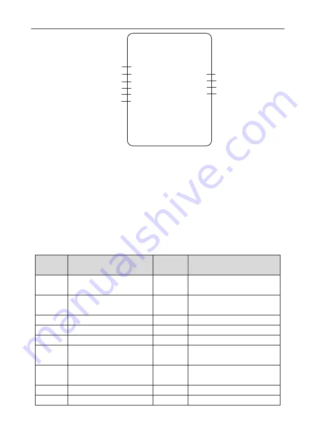
GD300-19 inverter
FWD running
S1
UP/DOWN terminal control reference
REV running
S2
Fault reset
S3
RO1
Brake output
RO2
Fault output
AO1 Running frequency
AO2
Current output
Frequency setting increasing (UP)
S4
Frequency setting decreasing (DOWN)
S5
Frequency reference
The mode is used in the case where the accerleration and deceleration commands are given by
button. Set P19.00 to
“5: Electromotion potentiometer mode”.
The forward and reverse direction signals of the hoist are given by S1 and S2, and the ACC/DEC
command is connected to S4 and S5. After start, if the ACC contact closes, the inverter will accelerate
toward 100% of speed ramp. If the ACC signal is canceled before reaching 100%, the inverter will
stop acceleration and run at current speed. If the ACC signal is given again, the inverter will continue
accelerating toward 100% speed. The DEC command goes similar to the ACC command.
If the direction command is canceled, the inverter will decelerate toward zero speed ramp. If the
direction command is closed before reaching zero speed, the inverter will stop deceleration and run at
current speed.
The parameters of electromotion potentiometer mode are as follows:
Function
code
Name
Function
selection
Function instruction
P00.01
Running command channel
1
Terminal
running
command
channel (LED flickering)
P08.44
UP/DOWN terminals control
0x010
UP/DOWN terminals setting is
valid
P05.01
S1 terminal function selection
1
Forward rotation operation (FWD)
P05.02
S2 terminal function selection
2
Reverse rotation operation (REV)
P05.03
S3 terminal function selection
7
Fault reset (RET)
P05.04
S4 terminal function selection
10
Frequency
setting
increasing
(UP)
P05.05
S5 terminal function selection
11
Frequency
setting decreasing
(DOWN)
P06.03
Relay RO1 output
5
Fault output
P06.04
Relay RO2 output
34
Brake control output


