Invacare Twister Service Manual Download Page 145

Twister / Twister Junior

Service Manual

Issued: 21.01.02 

Page 145 

 Note

:

Make sure that the earth cable is placed inside the bulb socket and does not touch the 
positive terminal (7) of the light bulb (4). 

 Note

:

check whether the bulb socket thread is oxidised. 

For this purpose, disassemble the headlight housing (see chapt. 15.6), clean thread if 
necessary and grease lightly. 

15.3.3   Reassembly of headlights 

• 

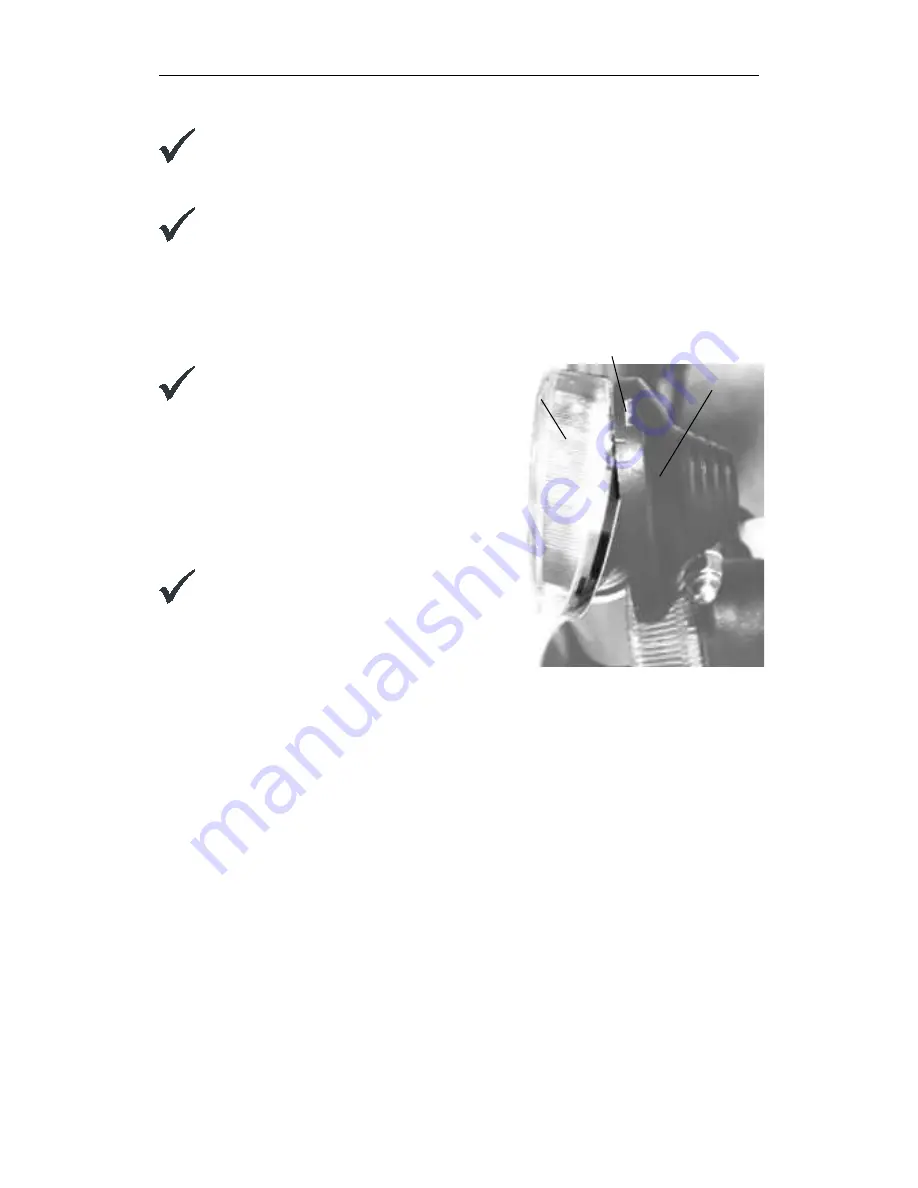
Mount the headlight glass (1) 

 Note

:

The tongue in the headlight glass (1) must 
engage with the headlight housing groove (5). 
See also Fig.  "Disassembled headlight" in 
chapter 15.3. 

• 

Check whether the contact (7) in the headlight 
housing is fitting closely to the light bulb positive 
terminal (4). 

• 

Fasten the headlight glass (1) using the tapping 
screw (2). 

 Note

:

The contact fits closely, when the headlight 
glass (1) must be inserted with a slight 
pressure.

1

5

Groove in headlight housing

Fit headlight glass

Summary of Contents for Twister

Page 1: ...Invacare TWISTER TWISTER JUNIOR SERVICE MANUAL These instructions contain information about Troubleshooting Testing of Components Repair Edition 10 2001 ...

Page 2: ...logue We reserve the right to make any alterations on the grounds of technical improvements The wheelchair may only be maintained and overhauled by qualified personnel The minimum requirement for service technicians is relevant training such as in the cycle or orthopaedic mechanics fields or suitably long term job experience Experience and knowledge of electrical measuring devices Multimeter is al...

Page 3: ...the original packaging for transport You should also include as accurate a fault description as possible The following symbols are used in these repair instructions Note This symbol identifies general information which indicates special points or simplifications in dismantling reassembly Caution It is imperative that you observe any safety instructions identified with this symbol ...

Page 4: ...DULE COMPOSITION 30 5 1 Wheelchair fittings without lighting system without actuators 30 5 2 Wheelchair fittings with 24 V lighting system without actuators 31 5 3 Wheelchair fittings without lighting with actuators 32 5 4 Wheelchair fittings with 24 V lighting with actuators 33 5 5 Wheelchair fittings with 12 V lighting TÜV Version without actuators 34 5 6 Wheelchair fittings with 12 V lighting T...

Page 5: ...assembly of legrests 59 9 7 Legrests with one piece footplate for shorter lower legs 60 9 7 1 Disassembly of legrests 62 9 7 2 Reassembly of legrests 62 9 8 Legrests 73 and 90 63 9 8 1 Disassembly of legrests 64 9 8 2 Reassembly of legrests 64 9 9 Headrest 65 9 9 1 Disassembly of headrest 66 9 9 2 Reassembly of headrest 66 9 10 Backrest anatomic element in standard pin dot and Dutch version 67 9 1...

Page 6: ...krest trunk supports 87 11 3 1 Disassembly of backrest trunk supports 88 11 3 2 Reassembly of backrest trunk supports 88 11 4 Electrical backrest adjustment Twister Junior 89 11 4 1 Disassembly of actuator motor 90 11 4 2 Reassembly of actuator motor 90 11 5 Manual backrest adjustment Twister Junior 91 11 5 1 Disassembly of backrest adjustment 92 11 5 2 Reassembly of backrest adjustment 92 11 6 Tw...

Page 7: ...ssembly of the wheel hubs 116 12 4 Drive unit complete 117 12 4 1 Dismounting the drive unit 121 12 4 2 Mounting the drive unit 121 12 5 Disengaging mechanism 122 12 5 1 Performance test of the disengaging mechanism 122 12 5 2 Adjusting the disengaging mechanism 123 12 5 3 Replacing the Star lock caps 123 12 6 Anti tip mechanism 124 12 6 1 Disassembly of the anti tip mechanism 124 12 6 2 Disassemb...

Page 8: ...46 15 4 2 Checking the rear lights 146 15 4 3 Reassembly of rear lights 146 15 5 Disassemble check direction indicators 147 15 5 1 Disassembly of direction indicators 147 15 5 2 Checking the direction indicators 148 15 5 3 Reassembly of the direction indicators 148 15 6 Disassembling headlight direction indicator unit completely 149 15 6 1 Disassembling the headlight 149 15 6 2 Reassembly of the h...

Page 9: ...wister Junior 160 17 5 4 Reassembly Twister Junior 160 17 6 Replacing actuator of automatic seat back adjustment or support tube for manual seat back adjustment 161 17 6 1 Disassembly 161 17 6 2 161 18 TESTING THE DRIVING ELECTRONICS 162 18 1 Overview of the electronic module and cable 162 18 2 Testing joystick boxes 164 18 2 1 Check power supply to joystick box 164 18 3 Check power module 166 18 ...

Page 10: ... control support 178 19 3 5 Disassembly of table plate and support 179 19 3 6 Reassembly of table plate and support 179 19 4 Chin control manually electrically swivelling in horizontal direction 180 19 4 1 Disassembly of control 182 19 4 2 Reassembling the control 182 19 4 3 Disassembly of the motor 183 19 4 4 Reassembly of the motor 183 19 4 5 Disassembly of the switchbox 183 19 4 6 Reassembly of...

Page 11: ...ST 21 3 LAYOUT OF MODULES COMPONENTS AND DISPLAYS AND CONTROLS 22 4 ELECTRONIC CONTROL COMPONENTS ACS 26 4 1 General 26 4 2 Module connection cables 28 4 3 Sensors 28 4 4 Status displays 28 5 MODULE COMPOSITION 30 5 1 Wheelchair fittings without lighting system without actuators 30 5 2 Wheelchair fittings with 24 V lighting system without actuators 31 5 3 Wheelchair fittings without lighting with ...

Page 12: ...sembly of legrests 54 9 4 2 Reassembly of legrests 54 9 5 Legrests electrically height adjustable 55 9 5 1 Disassembly of legrests 57 9 5 2 Reassembly of legrests 57 9 6 Legrest with one piece footplate 58 9 6 1 Disassembly of legrests 59 9 6 2 Reassembly of legrests 59 9 7 Legrests with one piece footplate for shorter lower legs 60 9 7 1 Disassembly of legrests 62 9 7 2 Reassembly of legrests 62 ...

Page 13: ...embly of the seat tilt adjustment 83 10 4 5 Disassembly of the seating module and the seat frame 83 10 4 6 Reassembly of the seating module and the seat frame 83 11 TESTING AND REPAIR WORKS ON RECARO SEATING SYSTEM 84 11 1 General 84 11 2 Twister Junior headrest 85 11 2 1 Disassembly of headrest 86 11 2 2 Reassembly of headrest 86 11 3 Twister Junior backrest trunk supports 87 11 3 1 Disassembly o...

Page 14: ...2 Splash protection for modules 113 12 2 1 Disassembly of Standard splash protection 113 12 2 2 Reassembly of Standard splash protection 113 12 2 3 Disassembly of the Lifter spray protection 113 12 2 4 Reassembly of Lifter splash protection 113 12 3 Drive wheels tyres and wheel hubs 114 12 3 1 Disassembly of drive wheels and tyres 115 12 3 2 Reassembly of drive wheels and tyres 116 12 3 3 Dismount...

Page 15: ...arging of fully discharged batteries 140 14 4 5 Performance test 141 15 TESTING AND REPAIR WORKS ON LIGHTING SYSTEM 142 15 1 Fault causes 142 15 2 Check lighting system 143 15 3 Disassemble check headlight 144 15 3 1 Disassembly of headlights 144 15 3 2 Checking the headlights 144 15 3 3 Reassembly of headlights 145 15 4 Disassembling checking rear lights 146 15 4 1 Disassembling rear lamps 146 15...

Page 16: ...2 2 Continuity check 156 17 2 3 Performance test 157 17 3 Replacing the actuator motors for the legrests 158 17 3 1 Disassembly 158 17 3 2 Reassembly 158 17 4 Replacing the seat adjustment actuator motor without lifter module 159 17 4 1 Disassembly 159 17 4 2 Reassembly 159 17 5 Replacement of seat adjustment with lifter module 160 17 5 1 Disassembly Twister 160 17 5 2 Reassembly Twister 160 17 5 ...

Page 17: ...of the joystick box holder for attendant 174 19 2 Joystick box for attendant 175 19 2 1 Disassembly of joystick box 176 19 2 2 Reassembly of the joystick box 176 19 2 3 Disassembly of the joystick box holder 176 19 2 4 Reassembly of joystick box holder 176 19 3 Table control central control 177 19 3 1 disassembly of joystick box 178 19 3 2 Reassembly of joystick box 178 19 3 3 Disassembly of centr...

Page 18: ...and lighting module with voltage converter 188 19 7 1 General 188 19 7 2 Removal of module 189 19 7 3 Refitting the module 189 20 CHECKING CABLES PLUGS AND SENSORS 190 20 1 General 190 20 2 Test procedure 190 20 2 1 Checking plugs and cables 190 20 2 2 Checking the sensors 191 21 WHEELCHAIR PROGRAMMING 192 21 1 General 192 21 2 Programming on the PC 193 21 3 Programming with the programming device...

Page 19: ...erating manual Observe the minimum requirements for carrying out the work See the chapter entitled General guidelines Caution Please note the high weight of some components This applies especially to removal of drive units and batteries The wheelchair must be switched off before removal of voltage carrying components To do this remove the battery When making measurements on voltage carrying compon...

Page 20: ...e with new Always use correctly dimensioned washers or spacers Note All plugs are fitted with mechanical safety devices which prevent release of the connecting plugs during operation To release the connecting plugs the safety devices must be pressed in When reassembling ensure that these safety devices are correctly engaged If the seating system is tipped forward for maintenance and service work i...

Page 21: ... flat nosed pliers circle pliers pointed pliers plumber s wrench cable lug pliers wooden or plastic hammer tyre repair kit commercial tyre pressure indicator valve removal tool wheel bearing puller Multimeter with probes and various cable clips jump leads soldering iron 30 W hot melt glue gun front wheel hub puller available from INVACARE Service circlip pliers for Star lock caps commercial e g Ti...

Page 22: ...llowing main subassemblies Chassis Seating system Power supply Drive control Lighting system Note Depending on the type of wheelchair the main subassemblies are equipped with different subassemblies legrests control elements seats etc 1 Seat cushion 2 Side panel upholstery 3 Backrest upholstery 4 Armrest 5 Side panel 6 Rear wheel 7 Battery 8 Front wheel 9 Footplates 10 Legrest 11 Standard joystick...

Page 23: ... Footplates 10 Legrest complete 11 Calf support 12 Lifter 13 Motor for seat tilt 14 Rear lights 15 Headlights 16 Direction indicators Twister configuration side view with Recaro seat lifter raised front wheel drive lighting system electrical Backrest adjustment electrical seat tilt height and tilt adjustable footrests swivelling joystick box and calf support without headrests 1 2 3 4 5 6 12 7 8 9 ...

Page 24: ...5 Battery 6 Front wheel 7 Footplates 8 Legrest 9 Standard joystick box 10 Calf support Twister configuration front view with KAB seat front wheel drive manually adjustable backrest manually adjustable seat tilting height and tilt adjustable footrests standard joystick box calf support without headrests 1 2 5 6 7 8 9 1 3 4 ...

Page 25: ...t with joystick box 8 Rear lights and direction indicators 9 Headlights and direction indicators 10 Rear wheel 11 Front wheel 12 Battery 13 Footplate 14 Calf strap 15 Legrest Twister Junior configuration with Junior seating system rear wheel drive adjustable backrest seat tilt height and lean adjustable footplate standard joystick box calf strap and headrest 1 2 4 3 6 7 8 10 11 12 13 14 15 5 9 ...

Page 26: ... individual components modules According to type the wheelchairs are equipped with different modules ACS Control module Module designation designation on module sticker Main module power module 24 Volt lighting module lighting actuator module combined lighting actuator module Standard joystick box DX REM 24 joystick box for attendant DX ACU 1AS Control unit for actuator motors DX ARC 5 ...

Page 27: ...ick box for Twister Junior G 80 I Chin control and switch joystick for Twister Junior Apart from its controlling functions the electronic control is in a position to perform the following additional functions Modules monitoring Actuator motor monitoring Drive system monitoring Fault diagnosis Note The control unit for the Recaro seat s adjustment functions is integrated in the seat and is not a pa...

Page 28: ...ergy can flow through the sensor In a vehicle with lifter information is passed using the sensor unit to the lifter positioning control and the seat tilting 4 4 Status displays Status displays are LEDs that point to errors in the wheelchair s electrical installation by means of blinking The following joystick boxes have a status display joystick box standard chin control table and central control ...

Page 29: ...ipped with an error memory which can be evaluated by means of a commercially available PC Additionally required hardware and software can be obtained from INVACARE Deutschland GmbH under Item No P10 076 Chin control Standard joystick Standard joystick box Joystick box for attendant ...

Page 30: ...pment consists of the power module with its joystick box The joystick box can be used for any available module that is not older than the original joystick box 5 1 Wheelchair fittings without lighting system without actuators Modules Main module power module Joystick box Cables BUS cable to joystick box Battery cable to joystick box Battery cable Main module ...

Page 31: ...h 24 V lighting system without actuators Module fittings Main module power module Combined lighting actuator module Joystick box Cables BUS cable to joystick box BUS cable from power module to lighting module Battery cable Lighting cable to joystick box Main Battery cable Lighting Lighting ...

Page 32: ... module Combined lighting actuator module Joystick box Control device for actuator motors Cables BUS cable to joystick box BUS cable from power module to lighting actuator module Battery cable Cable to actuators Cable to control unit for actuator motors to joystick box Lighting actuat or module Actuator motors Battery cable to joystick box Main module ...

Page 33: ...Combined lighting actuator module Joystick box Control device for actuator motors Cables BUS cable to joystick box BUS cable from power module to lighting actuator module Battery cable Cable to actuators Cable to control unit for actuator motors Lighting cable to joystick box to joystick box Actuator motors Lighting actuator module Lighting cable Battery cable ...

Page 34: ...e from power module to lighting module Battery cable Cable to microswitch Cable for additional power supply 12 V lighting Cable Additional Power Supply Serves to keep up the power supply of the 12 V lighting module in the event of a power failure via the ACS System BUS cable thus guaranteeing continued functioning of lights and warning flasher Battery cable Main module 12 V lighting module Additio...

Page 35: ...r module to Lighting actuator module BUS cable to lighting module Battery cable Cable to microswitch Cable for additional power supply 12 V lighting cable Cable for actuator motors Additional Power Supply Serves to keep up the 12 V lighting module power supply in the event of a power failure via the ACS System BUS cable thus guaranteeing continued functioning of lights and warning flasher Main mod...

Page 36: ...ain module power module DC DC Converter Joystick box Cables BUS cable to joystick box Battery cable Power supply cable for voltage converter with 15 A Fuse The voltage converter is for the RECARO Seat power supply Depending on the type of wheelchair additional equipment as indicated in chapters 5 3 and 5 2 can be added Main module to joystick box Connector to Recaro seat Battery cable 15 A fuse Vo...

Page 37: ...ng Tighten screws replace upholstery trunk support components 11 6 Twister Junior trunk support Check trunk support for damage and fastening Tighten screws replace components 11 3 All seats Check seams and for damage Check screw connections Check quick locks Replace parts Tighten screws Replace parts 9 10 9 10 9 10 Twister Junior seating unit Check seams and for damage Check screw connections Chec...

Page 38: ... through connections welded joints modules splash protection reflectors etc Tighten screws replace components 12 Wheel suspension and wheels Check shock absorbers for damage and function of Check drive wheels for tight fit and side play Check support wheels for tight fit float and side play Check support wheel forks Check tyres Replace Adjust replace wheel hubs Replace wheels wheel fork or wheel b...

Page 39: ...es Check for switched off drive control reduced speed during lifter operation Check for switched off drive control reduced speed during seat tilting 5 Charge replace batteries replace cables Replace lifter Replace worn or defective parts Use lubricant silicon oil Check replace cable magnet and speed sensor at lifter column Check replace cable magnet and speed sensor at lifter column 14 1 13 13 2 1...

Page 40: ...ng Check fixing Check cable plug connection Check drive lever function Check power supply Evaluate blinking code Tighten replace Replace Replace joystick box Replace cable connector plug or console 7 19 1 19 5 19 1 19 5 19 1 19 5 Twister Junior chin control and switch joystick Check function Check mechanics Replace if necessary Replace parts 19 1 19 5 11 13 Drive disabler Check function Replace jo...

Page 41: ...rs While doing this please note the references to the appropriate chapter in the manual or to the appropriate documentation 7 2 Fault causes Wheelchair will not start Engage motors Drive motors disengaged Bbatteries defective Replace batteries Delete status display on remote Pre charge batteries Completely discharge battery Check battery fuses Check voltage at operating console Power supply interr...

Page 42: ...ve Replace bulb Check replace cable connector plug Replace lighting actuator Bulb defective Cable connector plug defective Lighting actuator module defective Lighting unit defective Chapt 15 3 Chapt 20 Chapt 19 7 Check blink code at joystick box Replace lighting actuator module Replace actuator motor Lighting actuator module defective No blink codes Actuator motor defective One actuator motor does...

Page 43: ...hapt 19 1 Lifter not functioning Check replace cable connector plug Replace lifter module Cable connector plug defective Lifter module defective Chapt 20 Chapt 13 Vehicle does not run at reduced speed with raised lifter and or seat tilt above 5 Check replace cable connector plug Readjust distance Cable connector plug defective Distance between sensor and magnet less than 1 5 cm Chapt 20 Chapt Fehl...

Page 44: ...ick box status display blink codes Replace lighting actuator module Check replace cable connector plug Chapt 18 4 Chapt 20 The blink codes are only activated if the blink mechanism is switched on Check module status display replace if necessary Chapt 18 Electronics module defective 1 x blink Replace solenoid switch Replace blinker bulb Check lighting unit Replace actuator module Chapt 20 2 2 Chapt...

Page 45: ...otor Check motor brake engage motor Chapt 12 4 Chapt 16 4 Left hand motor brake defective Left hand motor disengaged 6 x blink Pre charge charge battery Chapt 14 4 314 4 4 Completely discharge battery 7 x blink Check battery charger Chapt 14 4 5 Compatibility problems between modules Drive motors temporarily overloaded Battery voltage too high 12 x blink 11 x blink 8 x blink Repair must be carried...

Page 46: ...screw M6x6 Loose damaged Tighten replace 4 Side panel holder Loose damaged Tighten replace 5 Side panel upholstery Damaged Replace 6 Insert ring Damaged Replace 7 Countersunk screw M5x20 Loose damaged Tighten replace 8 Insert ring caps Damaged Replace 9 Armrest holder Damaged Replace 10 Wing nut M6x10 Loose damaged Tighten replace 11 Armrest upholstery Damaged Replace 12 Machine screw M5x16 Damage...

Page 47: ...e grub screw 3 and armrest holder 9 Remove wing nut 10 and side panel holder 4 Remove insert ring caps 8 loosen countersunk screws 7 and remove side upholstery Loosen grub screw 3 and detach side panel attachment 9 9 1 2 Reassembly of armrests and side panels Reassembly takes place in the reverse order Note Hollow rivets can be replaced by plastic rivets or self tapping screws during reassembly if...

Page 48: ... belt for legrest Damaged Replace 2 Footplate short long Damaged Replace 3 Bottom part for legrests Damaged Replace 4 Top part for legrests Damaged Replace 5 Hexagon bolt M8x10 Loose damaged Tighten replace 6 Cover cap Damaged Replace 7 Slider Damaged Replace 8 Drilling screw tallow drop screw Loose damaged Tighten replace 1 7 4 5 6 3 6 7 8 8 3 5 2 ...

Page 49: ...l off footplate 2 from lower part of legrest 3 Remove hex head screw 5 and pull off lower part 3 from upper part of legrest 4 Sliders are inserted 7 and must be carefully levered out of the tube with a suitable tool such as a knife 9 2 2 Reassembly of legrests Reassembly takes place in the reverse order Note Observe part orientation while reassembling left hand right hand side Adjust legrests to i...

Page 50: ...ose damaged Tighten replace 6 Cover cap Damaged Replace 7 Slider Damaged Replace 8 Drilling screw with cheese head 4 2 x 13 Loose damaged Tighten replace 9 Slider Damaged Replace 10 Hexagon bolt M6x40 Loose damaged Tighten replace 11 Hexagon nut M6 Loose damaged Tighten replace 12 Hexagon bolt M6x45 Loose damaged Tighten replace 13 Round washer6x17x2 5 Damaged Replace 14 Hexagon nut M6 self lockin...

Page 51: ...ew 5 and pull off lower part 3 from upper part of legrest 4 Remove hex bolt 12 and detach footplate tube 15 If necessary detach sliders 7 9 carefully from the tube using a sharp object such as a knife 9 3 2 Reassembly of legrests Reassembly takes place in the reverse order Note After reassembly footplate tilt must be readjusted using the hex bolt 10 Secure using hex nut 11 Observe part orientation...

Page 52: ...amaged Replace 7 Calf support holder Damaged Replace 8 Guide bar Damaged Replace 9 Release lever Damaged Replace 10 Hexagon cap nut M6 self locking Loose damaged Replace 11 Housing for back locking Damaged Replace 12 Spring for back locking Damaged Replace 13 Unlocking plate for back locking Damaged Replace 14 Unlocking block for back locking Damaged Replace 15 Hexagon cap nut M6 self locking Loos...

Page 53: ...Slider SL Damaged Replace 27 Allen cylinder head screw M6 Loose damaged Tighten replace 28 Calf support joint for legrest Damaged Replace 29 Bush rd plastic Damaged Replace 30 Machine screw M6 Loose damaged Tighten replace 31 Hexagon nut M6 self locking Loose damaged Replace 32 Cover cap Damaged Replace 33 Hexagon cap nut M6 self locking Loose damaged Replace 34 Washer Damaged Replace 35 Washer Da...

Page 54: ...ew 30 and detach calf support Loosen cheese head screw and remove calf support holder 7 from legrest calf support joint Loosen release lever 9 and pull off from legrest rocker 2 Back locking 11 15 If necessary detach sliders 7 9 carefully from the tube using a sharp object such as a knife 9 4 2 Reassembly of legrests Reassembly takes place in the reverse order After reassembly footplate tilt must ...

Page 55: ... locking Loose damaged Replace 7 Joint cap with countersunk hole Damaged Replace 8 Joint cap with hex hole Damaged Replace 9 Cylinder head screw with Allen key Loose damaged Tighten replace 10 Countersunk screw M6 40 Loose damaged Tighten replace 11 Hexagon cap nut M5 self locking Loose damaged Replace 12 Cheese head screw M5 25 Phillips head Loose damaged Tighten replace 13 Attachment tube Damage...

Page 56: ...oose damaged Replace 24 Washer Damaged Replace 25 Phillips head machine screw M5 16 Loose damaged Tighten replace 26 Calf support holder Damaged Replace 27 Calf support Damaged Replace 28 Slider Damaged Replace 29 Footplate long short Damaged Replace 30 Footplate tube Damaged Replace 31 Drilling screw with cheese head 4 2 x 13 Loose damaged Tighten replace 32 Hexagon nut M8 self locking Loose dama...

Page 57: ...etach footplate 29 from footplate tube 30 Loosen raised head screws 12 completely and remove together with nuts 11 from clamping piece 21 Detach clamping piece 21 completely with calf support 27 from legrest rocker 16 Loosen raised head Phillips screws 25 and separate calf support holder 26 from calf support 27 Remove cap 22 loosen nut 23 and detach together with washer 24 Remove calf support hold...

Page 58: ...her Damaged Replace 4 Cap nut M8 Loose damaged Tighten replace 5 Cover cap Damaged Replace 6 18 5 mm push in tube Damaged Replace 7 Sport footplate aluminium Damaged Replace 8 Rubber mat glued Damaged Replace 9 Leaf spring Damaged Replace 10 Self tapping screw 4 2 16 Loose damaged Tighten replace 11 Slider Damaged Replace 12 Calf strap Damaged Replace 13 Legrest upper part left Damaged Replace 7 5...

Page 59: ...he upper part of the legrest 13 out of the insertion tube 6 Loosen clamp 2 and detach from the upper part of the legrest 13 Loosen self tapping screw 10 completely and pull the insertion tube 6 out of the footplate 7 Remove leaf spring 9 out of the footplate 7 If necessary pull off slider 11 and caps 5 from the insertion tube 6 9 6 2 Reassembly of legrests Reassembly takes place in the reverse ord...

Page 60: ...d Replace 2 Hexagon bolt M8 x 120 Loose damaged Tighten replace 3 Slider Damaged Replace 4 Cap nut M8 Loose damaged Tighten replace 5 Washer Damaged Replace 6 Clamp 22 mm Loose damaged Tighten replace 7 Hexagon bolt M8 x 25 Loose damaged Tighten replace 8 Push in tube Damaged Replace 10 7 5 6 4 8 14 16 15 18 17 19 29 28 27 26 25 24 23 22 21 20 13 12 11 10 9 3 2 1 ...

Page 61: ... M6 Loose damaged Tighten replace 16 Countersunk screw M8 40 Loose damaged Tighten replace 17 Width compensation Damaged Replace 18 Nut M8 Loose damaged Tighten replace 19 Cover cap Damaged Replace 20 Bush 15 22 8 3 Damaged Replace 21 Self tapping screw 6 4 2 13 Loose damaged Tighten replace 22 Footplate attachment Damaged Replace 23 Cover cap Damaged Replace 24 Slider Damaged Replace 25 Cone Dama...

Page 62: ...grest Loosen self tapping screw 21 completely and pull footplate attachment 22 with width compensation 17 from the footplate 11 Remove leaf spring 13 out of the footplate 11 The two following steps apply to both legrests Remove cap 19 detach nut 18 from countersunk screw 16 and remove footplate attachment 22 with bush 27 from width compensation 17 If necessary unscrew regulating screw 14 with coun...

Page 63: ...e damaged Tighten replace 7 2 washer Damaged Replace 8 Self tapping screw 4 2 13 Loose damaged Tighten replace 9 Nut M6 Loose damaged Tighten replace 10 Regulating screw M6 40 Loose damaged Tighten replace 11 Screw M6 45 Loose damaged Tighten replace 12 Calf strap Damaged Replace 13 Legrest lower part Damaged Replace 14 Cover cap Damaged Replace 15 Screw M8 10 Loose damaged Tighten replace 16 Legr...

Page 64: ... the screw 11 Detach screw 11 with washer 7 and separate footplate tube 4 from the lower part of the legrest 13 If necessary loosen nut 9 and remove together with regulating screw 10 If necessary remove sliders 5 and caps 14 The sliders are inserted They can be levered off using a suitable tool such as a screwdriver If necessary loosen screw 3 and detach guard roller 2 from the footplate 1 9 8 2 R...

Page 65: ...s head screws M4 15 Loose damaged Tighten replace 8 Headrest shell Damaged Replace 9 Headrest upholstery Damaged Replace 10 Nut M8 self locking Loose damaged Tighten replace 11 2x linings 8 5 13 Damaged Replace 12 Headrest arm attachment Damaged Replace 13 Hexagon bolt M8 x 50 Loose damaged Tighten replace 14 Washer Damaged Replace 15 Nut M5 self locking Loose damaged Tighten replace 16 Clamp term...

Page 66: ...eadrest shell 8 together with headrest arm 5 from the headrest holder Detach screw 14 with bushes 12 and washers 22 plus headrest arm 5 from the headrest shell 8 Loosen slotted screws 7 and detach headrest arm attachment 13 from the headrest shell 8 Detach protecting caps 16 loosen nut 17 from screw 2 and remove screw with washers 18 Detach headrest holder from clamping piece 20 Remove Allen screw...

Page 67: ...lt M8 x 50 Loose damaged Tighten replace 4 4 washer 21 8 3 1 5 Damaged Replace 5 Nut M8 self locking Loose damaged Tighten replace 6 Seat belt Damaged Replace 7 Backrest frame tube Damaged Replace 8 Backrest belt Damaged Replace 9 Backrest upholstery Damaged Replace 10 Self tapping screw with cap Loose damaged Tighten replace The backrest element can be equipped with a backrest upholstery 9 or wit...

Page 68: ...e tube or remove tapping screws with caps 10 and detach backrest upholstery 9 from the backrest frame tube 5 Loosen nuts 10 completely Remove screws 3 with washers 4 and detach backrest element holder 6 from seat frame Caution Only detach one backrest element holder from seat frame at a time If both backrest element holders are removed at the same time the seat frame will only be supported by the ...

Page 69: ...rt version Component Check Remedy 1 Backrest frame tube Damaged Replace 2 2 Hexagon bolt M8 x 45 Loose damaged Tighten replace 3 2 washer 16 8 3 1 5 Damaged Replace 4 4 washer 24 8 3 2 Damaged Replace 5 2 x lining Damaged Replace 6 2 x locknut M8 Loose damaged Replace 3 6 16 14 15 14 13 17 20 18 19 21 22 1 2 3 4 5 8 7 11 23 24 25 ...

Page 70: ...e 16 Support bracket Damaged Replace 17 Seat belt Damaged Replace 18 Backrest belt Damaged Replace 19 4 x self tapping screw with cap Damaged Replace 20 Backrest upholstery Damaged Replace 21 4 x clamping piece Loose damaged Tighten replace 22 8 x countersunk self tapping screw 4 8x17 Loose damaged Tighten replace 23 Extension for lift motor Loose damaged Tighten replace 24 Locking washer Damaged ...

Page 71: ...s in the backrest frame tube 1 Note The bushes can only be removed from the inside to the outside Loosen tapping screws 19 completely and detach the backrest belt 18 from the backrest frame tube 1 or press backrest upholstery 20 from the backrest frame tube 1 Note The backrest upholstery can also be removed while the backrest frame tube is being mounted If necessary remove countersunk tapping scre...

Page 72: ...ace 5 2 x Bush 12x8 5x23 Damaged Replace 6 2 x locknut M8 Loose damaged Replace 7 Seat belt Damaged Replace 8 4 x hexagon bolt M8x50 Loose damaged Tighten replace 9 2 x washer 16x8 3x1 5 Damaged Replace 10 4 x locknut M8 Loose damaged Replace 11 Support bracket Damaged Replace 12 Trigger unit Loose damaged Tighten replace 13 Bracket Loose damaged Tighten replace 14 Slider Damaged Replace 15 2 x ma...

Page 73: ...re to the indicated steps The gas pressure spring and the Bowden cable for example can be dismounted without having first to remove the entire backrest frame If existing remove headrest first See chapter 9 9 Remove the quick release bolt 16 located on the lower part of the backrest frame tube 1 Loosen nut 18 on the lower part of the support bracket 11 completely and detach together with washer 19 ...

Page 74: ...e lever 12 Pinch off caps 25 and pull the Bowden cable 20 out of its cover 24 Caution Do not remove the support bracket 11 completely otherwise the seat frame will only be supported by the threaded spindle or by the seat tilt adjustment actuator and will therefore be unstable 9 12 2 Reassembly of the backrest elements Reassembly takes place in the reverse order Note The release lever Bowden cable ...

Page 75: ... holder Loose damaged Tighten replace 7 Screws Damaged Replace 9 13 1 Disassembly of expansion wedge Loosen wing screws 2 and separate insertion tubes from each other Loosen screws 7 and detach wedge shaped bolster 1 from the insertion tube 3 If necessary lift seating system electrically or manually and lock if necessary Loosen screws 7 and detach expansion wedge holder 6 from seat frame 9 13 2 Re...

Page 76: ...he legrests see steps described in chapter 9 10 2 Headrest safety belt and push handle Component Check Remedy 1 Headrest Damaged Replace 2 Backrest module Damaged Replace 3 Handle Damaged Replace 4 Push bar Damaged Replace 5 Holder for push handle Damaged Replace 6 Clamping lever M6 x 10 Loose damaged Tighten replace 7 4 x washer Damaged Replace 8 4 x screw M6 Loose damaged Tighten replace 9 Seat ...

Page 77: ...e clamps under the guide tubes and pull headrest 1 upwards out of the backrest module 2 Loosen four screws at the back of the backrest module 2 and detach safety belt 9 Loosen clamping lever 6 and detach push bar 4 with handle 3 from its holder 5 If necessary pull handle 3 from the push bar 4 Loosen four screws 8 with washers 7 completely and detach holder 5 from backrest module 2 10 2 2 Disassemb...

Page 78: ...d Tighten replace 5 Adapter Damaged Replace 6 Mirror holder Damaged Replace 7 Mirror Loose damaged Tighten replace 8 Collar clamp clamping screw Loose damaged Tighten replace 9 Cover cap Damaged Replace 10 Armrest attachment Damaged Replace 11 Wing nut Loose damaged Tighten replace 12 Armrest holder Damaged Replace 13 Clamping lever Loose damaged Tighten replace 14 Slider Damaged Replace 15 Seat f...

Page 79: ...6 completely and detach mirror 7 with clamp clamp screw and washers 8 from the mirror holder 6 Loosen wing nut 11 and clamping lever 13 and detach attachment 3 with upholstery 1 plus attachment 10 completely from holder 12 If necessary loosen screws 2 and separate upholstery 1 from attachment 4 Loosen wing nut 13 at lower part of seat frame 15 and remove armrest holder 12 from seat frame 15 10 3 2...

Page 80: ...anual adjustment can be mounted Component Check Remedy 1 Seating module LX Damaged Replace 2 Backrest module LX Damaged Replace 3 Headrest LX or DS Loose damaged Tighten replace 4 Backrest module fastening Damaged Replace 30 1 6 4 1 5 10 11 3 3 8 2 7 6 5 4 15 13 14 10 12 18 17 19 20 22 27 27 26 28 21 24 23 7 9 25 16 31 29 32 33 34 11 ...

Page 81: ...amaged Replace 17 4 x 4 8 x 16 screws Loose damaged Tighten replace 18 2 x seat adapter front Damaged Replace 19 2 X hinge bolts 7 8x30 Damaged Replace 20 2 X hinge bolts 7 8x35 Damaged Replace 21 2 x limit stop plate Damaged Replace 22 4 x locknut M6 Loose damaged Tighten replace 23 Actuator motor Damaged Replace 24 Connection plug Loose damaged Tighten replace 25 Quick release bolt Damaged Repla...

Page 82: ...he Recaro seat remove the spring loaded catches 11 and lift the Recaro seat completely off the chassis 10 4 1 Disassembly of legrests If necessary loosen the actuator motor electrical connections Legrest adjustment Release legrest lock and detach legrests Use a suitable sleeve such as a leather strip and hold the locking device bolt with pliers Loosen nut M5 completely and detach together with bol...

Page 83: ... 5 Disassembly of the seating module and the seat frame If necessary remove headrest For more information see chapter 10 2 Detach the joystick box and if existing the brake lever from the side panels Detach the side panels from the seat frame 10 For more information see chapter 10 3 If necessary detach the actuator motor connection cables and take off the clamping pieces Release legrest lock and d...

Page 84: ... Seating Systems The Junior seating system consists of the following components 1 Junior seating system 2 Junior headrest complete 3 Junior backrest unit complete 4 Legrest attachment 5 Legrest upper part complete 6 Junior Expanding wedge complete 7 Junior footplate complete 8 Legrest attachment 9 Legrest upper part complete 10 Seat support with cushion and lifter fitted 11 Actuator motor or gas p...

Page 85: ...ed Replace 6 Headrest Damaged Replace 7 Headrest attachment Damaged Replace 8 Clamping lever M6 x 25 Damaged Replace 9 Height adjustment Damaged Replace 10 Allen screw M6 x 25 Damaged Replace Note The headrest attachment is fixed to the backrest tubes with four and M6 x 12 Allen screws and 6 4 mm washers Two M6 x 20 screws are also provided for fixing the push handle Screws washers and push handle...

Page 86: ...drest and the depth adjuster can be separated Remove the slider 3 from the height and depth adjuster Loosen screw fixings with spanner 30 mm and pull out actuator motor or gas pressure spring upwards so that the headrest attachment is freed Remove the two screws M6 x 20 at the rear of the headrest attachments with an Allen key 4 mm and remove the push handle Remove the four screws M6 x 12 at the r...

Page 87: ...ged Replace 2 Washer 6 4 x 12 5 x 1 6 Damaged Replace 3 Trunk support set Damaged Replace 4 Trunk support cover Damaged Replace 5 Cheese head screw M6 x 16 Damaged Replace 6 Trunk support attachment Damaged Replace Note The trunk support attachment 6 is used in two versions length 215 mm or length 155 mm depending on the seat width 1 2 3 3 4 4 5 5 2 2 6 7 ...

Page 88: ...runk support attachment 6 together with washers 2 and trunk support set Loosen screws 5 with Allen key 4 mm and remove together with washers 2 so that the trunk support attachment is freed Remove trunk support attachment from the backrest tube 11 3 2 Reassembly of backrest trunk supports Reassembly takes place in the reverse order Note After reassembly the trunk supports must be individually adjus...

Page 89: ...2 Hexagon bolt M8 x 40 Damaged Replace 3 Washer 8 4 x 17 x 1 6 Damaged Replace 4 Bush rd 10 X 1 X 26 Damaged Replace 5 Nut M8 self locking Released Always replace 6 Quick release bolt Damaged Replace 7 Cable with connector plug and tension relief Damaged Replace motor Note Not all the wheelchair variations require the extension for the lift motor 1 2 3 4 3 5 6 7 8 9 10 ...

Page 90: ... binders if present Loosen bolt 2 and nut 5 with 13 mm spanner and remove together with washers 3 and bush 4 from the headrest attachment 8 on the backrest tubes 9 Loosen quick release bolts 6 and remove actuator motor 1 11 4 2 Reassembly of actuator motor Reassembly takes place in the reverse order Caution The nut 5 must always be replaced ...

Page 91: ...d Replace 5 Lining Damaged Replace 6 Hexagon bolt M8 x 30 12 9 Damaged Replace 7 Countersunk screw M5 x 16 Damaged Replace 8 External clamp Damaged Replace 9 Allen screw M6 x 25 Damaged Replace 10 Release lever attachment Damaged Replace 11 Unlatching unit LH RH Damaged Replace 12 Inside clamp Damaged Replace 13 Quick release bolt Damaged Replace 14 Hexagon bolt M8 x 40 Damaged Replace 15 Adapter ...

Page 92: ... backrest adjustment Loosen bolt 14 and nut 17 at remove together with washers 16 so that the adapter 15 can be removed from the gas pressure spring Hold the fork piece 1 firmly unscrew the gas pressure spring 19 from the fork piece and remove Loosen bolt 4 and nut 21 and separate brace 3 from fork piece 1 Pinch and remove end caps 22 from inside Bowden cable if necessary loosen clamping screws 2 ...

Page 93: ...ged Replace 6 Armrest tube Damaged Replace 7 Trunk support cover Damaged Replace 8 Slider SL 22 Damaged Replace 9 Cheese head screw M6 x 12 Damaged Replace 10 Allen screw M5 x 40 Damaged Replace 11 Lateral trunk support attachment Damaged Replace 12 Circular washer Damaged Replace 13 Trunk support upholstery Damaged Replace 14 Allen screw M5 x 12 Damaged Replace 15 Hexagon nut M8 Released Always r...

Page 94: ...Twister Twister Junior Service Manual Page 94 Issued 21 01 02 Note The armrest holder width 2 is dependent on the seat width SB 25 SB 30 and SB 35 ...

Page 95: ...the trunk support padding 13 can be separated from the attachment 11 Opened the zips and remove the trunk support cover 7 from the trunk support padding 13 Loosen nut 15 with 13 mm spanner and pull the armrest tube 6 together with locking washer 3 out of the armrest holder 2 Completely release Allen screws 5 with 6 mm spanner and remove bolts 5 with washer 4 and locking washer 3 from the armrest t...

Page 96: ...rew 5 x 20 Damaged Replace 9 Backrest upholstery attachment Damaged Replace 10 Seat belt Damaged Replace 11 Backrest upholstery Damaged Replace 12 Nut M8 self locking Released Always replace 13 Headed liner 12 x 1 8 x 19 7 Damaged Replace 14 Backrest adjustment attachment Damaged Replace 15 Washer 8 4 x 17 x 1 7 Damaged Replace 16 Hexagon bolt M8 x 35 Damaged Replace 17 Washer 8 4 x 25 x Damaged R...

Page 97: ...screws 8 with a Phillips screwdriver so that the backrest upholstery 11 can be removed Loosen bolts 18 and nuts 12 with 13 mm spanner and remove together with washers 15 and 17 and bushes 19 so that the safety belts 10 and 20 can be removed Loosen bolts 16 and nuts with 13 mm spanner and remove together with washers 15 so that the backrest adjustment attachment 14 can be removed from the seat supp...

Page 98: ...s Nut is loosened Always replace 11 8 1 Disassembly of the expanding wedge Loosen bolt 6 with 4 mm spanner and separate upper part attachment 2 from lower part attachment 7 Open Velcro fastening and pull expanding wedge cover 5 out of expanding wedge upholstery 4 Loosen two countersunk screws 3 and separate upper part attachment 2 from expansion wedge upholstery 4 Loosen four screws 8 and remove f...

Page 99: ...Twister Twister Junior Service Manual Issued 21 01 02 Page 99 Caution The self locking nut 10 must always be replaced ...

Page 100: ...Damaged Replace 7 Allen screw M10 x 35 Damaged Replace 8 Seat support Damaged Replace 9 Grub screw M8 x 10 Damaged Replace 10 Bush 10 x 1 x 26 Damaged Replace 11 Washer 8 4 x 17 x 1 6 Damaged Replace 12 Hexagon bolt M8 x 40 Damaged Replace 13 Slider SL 16 Damaged Replace 14 Bush BB 1209 DU Damaged Replace 15 Lining 12 x 8 1 x 22 8 Damaged Replace 16 Hexagon bolt M8 x 35 Damaged Replace 17 Allen sc...

Page 101: ... straps 5 towards the rear Remove the connector plug from the adapter 20 if necessary loosen bolts 2 with a 3 mm spanner and nuts 19 with a 6 mm spanner and separate the adapter 20 from the seat plate 3 Loosen screws 1 and detach seat plate 3 from the seat support 8 Remove plug from Montreal 21 if necessary loosen bolts 17 with 4 mm spanner and remove module 21 from seat support 8 Loosen bolt 12 w...

Page 102: ...ged Replace 7 Hexagon bolt M8 x 16 Damaged Replace 8 Footplate attachment Damaged Replace 9 Allen screws M6 x 35 Damaged Replace 10 RH bracket for footplate attachment Damaged Replace 11 Bush BB 0608 DU Damaged Replace 12 LH bracket for footplate attachment Damaged Replace 13 Nut M6 self locking Released Always replace 14 Adjustment plate Damaged Replace 15 Allen screw M5 x 10 Damaged Replace 16 F...

Page 103: ...sert tube 6 can be separated from the brackets 10 and 12 Loosen bolts 9 and nuts 13 with 5 mm spanner so that the bracket 12 can be removed from the footplate attachment 8 or so that the bracket 10 can be separated together with bolt 9 and nut 13 Remove expanding rivets 3 with a knife so that the rubber cover 4 can be removed from the footplate 16 Note the fitting positions of the footplate 16 adj...

Page 104: ...sion spring Damaged Replace 6 Locking lever Damaged Replace 7 Plunger rod Damaged Replace 8 Release button Damaged Replace 9 Legrest shell LH Damaged Replace 10 Nut M8 self locking Released Always replace 11 Nut M5 self locking Released Always replace 12 Straight pin RD 5 x 32 DIN 7 Damaged Replace 13 Nut M6 SP14 Damaged Replace 14 Allen screw M6 x 16 Damaged Replace 15 Allen screw M5 x 25 Damaged...

Page 105: ...Twister Twister Junior Service Manual Issued 21 01 02 Page 105 Note Both legrest upper parts are of identical construction ...

Page 106: ...th nut 10 Loosen bolts 15 with 4 mm spanner and remove together with nuts 11 Separate the legrest shells 1 and 9 Ensure that no individual parts are lost while doing this Replace defective individual parts if necessary Caution The press cones 2 must be removed with a pulling tool 11 11 2 Reassembly of legrest upper parts Reassembly takes place in the reverse order Caution The self locking nuts 10 ...

Page 107: ...aged Replace 6 Legrest cover RH LH Damaged Replace 7 Footrest adapter Damaged Replace 8 Legrest contact Damaged Replace 9 Self tapping screw 4 x 12 not illustrated Damaged Replace Note Both legrest attachments are of identical construction The inserts are supplied in lengths of 150 mm or 215 mm depending on the seat widths The legrest contacts 8 are available in lengths of 300 or 700 mm including ...

Page 108: ...and remove the legrest attachments Loosen bolts 2 with a 4 mm spanner and take the legrest adapter 7 off the legrest attachment 3 Pull out the Pine Tree clips and remove the legrest cover 6 from the legrest attachment 3 Loosen bolts 4 with a 5 mm spanner and take the insert 1 off the legrest attachment 3 11 12 2 Reassembly of legrest attachments Reassembly takes place in the reverse order Caution ...

Page 109: ...Junior Component Check Remedy 1 Switch joystick Damaged Replace 2 Chin control Damaged Replace 3 Clamping screw Damaged Replace 4 Swivel arm Damaged Replace 5 Fixing and joint Damaged Replace 6 Allen screw Damaged Replace 7 4 Allen screws Damaged Replace 8 Attachment for swivel arm Damaged Replace 2 6 7 1 3 4 5 8 9 ...

Page 110: ...1 Loosen the fixings and disassemble the hinge together with both swivel arm tubes 4 Remove the connecting cable from the tubes at this stage Loosen the clamping screw 3 and remove the switch joystick 1 with chin control 2 from the swivel arm Loosen screws 7 with 4 mm spanner and remove attachment 8 from backrest tubes 9 11 13 2 Reassembly of the chin control and switch joystick Reassembly takes p...

Page 111: ...ten replace 13 Hexagon cap nut M6 self locking Loose damaged Replace 14 Housing for front wheel suspension Damaged Replace 15 Lining Damaged Replace 16 Spring plate Damaged Replace 17 Pressure spring Damaged Replace 18 Axle for front wheel suspension Damaged Replace 19 Lining Damaged Replace 20 Spring barrel Damaged Replace 21 Rubber gasket Damaged Replace 22 Drill hole in axle for front wheel sus...

Page 112: ...el fork 14 and the housing for front wheel suspension 6 are now separated Detach bush 7 spring plate 8 compression spring 9 bush 11 spring box 12 and rubber ring 13 from the front wheel fork 14 Guide a suitable pin 6 mm through the drillhole 14 in the axle for front wheel suspension 10 and use it as a lever for countering when loosening the hexagon nut 19 SW 19 Note The diameter of the pin must be...

Page 113: ...or more information see chapter 13 Note For testing procedures on the drive electronics and the modules or for the conversion from front wheel drive to rear wheel drive and vice versa it would be advisable to tie the chassis central covering 1 up You could for example use a cable binder at the spring connector 4 on the attachment for the motor or on the tube used to adjust the seat tilt On the Twi...

Page 114: ...n key M8 x 20 Loose damaged Tighten replace 4 Wheel rim body outer Damaged Replace 5 Hose Damaged porous Replace 6 Casing Damaged nails broken glass worn out porous Replace 7 Wheel rim body inner Damaged Replace 8 Wheel hub Damaged Replace 9 Cylinder head screw with Allen key M6 x 35 Loose damaged Tighten replace Note The wheel hubs can be detached completely with mounted drive wheels and tyres Se...

Page 115: ... support such as a wooden block to prop up the vehicle so that the drive wheels are not loaded Unscrew countersunk screw 3 complete and remove drive gear Caution Risk of accidents Before proceeding to the next step it is imperative to deflate the tire by pressing in the valve tappet Loosen the cheese head screws 9 and detach the two rim halves 4 7 from the outer cover 6 Remove the inner tube 5 fro...

Page 116: ...e the Allen screws 3 under any circumstances During factory assembly they are inserted with Plasbolt and can be dismantled reassembled up to 6 times At the seventh reassembly at the latest the bolts must be cleaned and then smeared with Loctite 12 3 3 Dismounting of the wheel hubs Engage motor Place the vehicle on its side on some form of padding so that the drive wheel to be removed is on top or ...

Page 117: ...Twister Twister Junior Service Manual Issued 21 01 02 Page 117 12 4 Drive unit complete ...

Page 118: ...Twister Twister Junior Service Manual Page 118 Issued 21 01 02 1 2 3 4 6 8 7 9 5 10 11 12 13 16 15 14 17 12 ...

Page 119: ...Twister Twister Junior Service Manual Issued 21 01 02 Page 119 ...

Page 120: ...me tube left Damaged Replace 7 Special sliding block Damaged Replace 8 Washer 6 4x12 5 1 6 Damaged Replace 9 Countersunk screw with Allen key M6x45 Loose damaged Tighten replace 10 Cheese head bolt with Allen key M6x45 Loose damaged Tighten replace 11 Spacer Damaged Replace 12 Main frame for battery and lifter Damaged Replace 13 Clutch rod left Damaged bent Replace straighten 14 Motor clutch lever...

Page 121: ...ing pliers the cable binder by which the control cable is attached to the main frame Remove cheese head Allen screws 10 and countersunk Allen screws 9 and detach motor and distance place from the main frame 12 Note In a vehicle with rear wheel drive the guide tube for the anti tip mechanism is mounted between the motor 15 and the tube frame 6 instead of the distance plate 11 Also see in this respe...

Page 122: ...Prop up vehicle in order to relieve the drive wheels Bring shift lever into a horizontal position Neither of the drive wheels should be able to be turned by hand Bring the shift lever gradually into a vertical position while you are trying to rotate the drive wheels Both drive wheels should be disengaged more or less simultaneously in other words should start to turn more or less simultaneously No...

Page 123: ...g shift lever 1 into a horizontal position Engage both motors via the clutch rods against the limit stop Tighten the regulating screws 8 again Test performance See chapter 12 5 1 12 5 3 Replacing the Star lock caps Remove old Star lock caps Fit the Star lock cap 2 into the Star lock pliers 1 and position the pliers correctly over the clutch rod and release lever see positions 1 and 2 or6 122 Tight...

Page 124: ...e anti tip mechanism The drive unit must be removed before disassembling the anti tip mechanism See chapter 12 4 1 Loosen the cheese head screws 7 Remove the support wheels 4 with bushes 2 and washers 6 If necessary remove sliders 5 12 6 2 Disassembly of the anti tip mechanism Check the support wheels for damage replace if necessary Check the guide tubes for deformations replace if necessary 12 6 ...

Page 125: ...left from the main frame aluminium section Pos 6 in chapter 12 4 If existing change lighting system lamps diagonally Loosen that clamping screws Pos 4 in chapter 12 4 under the aluminium section Push the aluminium section Pos 6 in chapter 12 4 to the front until the motor fixing screws Pos 9 10 chapter 12 4 are visible Remove motor screws Replace the spacers Pos 11 in chapter 12 4 with the anti ti...

Page 126: ...ting unit See Twister operating manual chapter 10 Disassembling for Transport Detach chassis central covers and side covers See also chapter 12 2 Separate cable connections to lifter 1 Loosen 4 nuts 2 detach together with lifter pillar 1 Unscrew power module and shielding plate and mount again to opposite side Always in the back in driving direction See also chapter 19 6 Re lay connection cable re...

Page 127: ...th the anti tip mechanism See chapter 12 6 Screw motors and anti tip wheels again to the lower part of the frame tubes Lay cables in a way so that they cannot get pinched or rub against other parts and fix anew with cable binders Caution Pay attention to the wheelbase Vehicles with front wheel drive and lifter are supplied as standard with the motor in the forward position i e with longer wheelbas...

Page 128: ...m section Pos 6 in chapter 12 4 If existing change lighting system lamps diagonally Loosen the clamping screws Pos 4 in chapter 12 4 under the aluminium section Push the aluminium section Pos 6 in chapter 12 4 to the front until the motor fixing screws Pos 9 10 chapter 12 4 are visible Remove motor screws Replace the anti tip mechanism Pos 11 in chapter 12 4 with the spacers See also chapter 12 6 ...

Page 129: ...ng for Transport Detach chassis central covers and side covers See also chapter 12 2 Separate cable connections to lifter 1 Loosen 4 nuts 2 detach together with lifter pillar 1 Unscrew power module and shielding plate and mount again to opposite side Always in the back in driving direction See also chapter 19 6 Re lay connection cable re fix with cable binders and connect again with power module U...

Page 130: ...hapter 12 4 are visible Remove motor screws Replace the anti tip mechanism Pos 11 in chapter 12 4 with the spacers See chapter 12 6 Screw motors and anti tip mechanism again to the lower side of the frame tubes Lay cables in a way so that they cannot get pinched or rub against other parts and fix anew with cable binders Caution Pay attention to the wheelbase Vehicles with front wheel drive and lif...

Page 131: ...3 M8x16 Installation of 4 washers DIN 125 M5 at the splash protection fastening Fitting a spacer in the splash protection mentioned above Fitting a cable clip in the splash protection mentioned above Replacement of the cable at the adapter box See chapter 5 Pos 1 4 in spare parts catalogue 13 3 1 Instructions for retrofitting the lifter module Remove the lifter module from the vehicle 9 Note The r...

Page 132: ... the nut heads Insert the cable which leads to the lifter column into the cable clip Release the four adapter box screws Pos 6 in chapter 13 2 2 Loosen the two inner screws in the adapter box and detach it Detach the cable grey from pin 11 and the cable black from pin 12 both leading into the lifter column from the socket by means of a special tool Remove cables and box Attach the new adapter box ...

Page 133: ...ng below 23 V the power supply to the motors will be interrupted and the display on the joystick box will be blinking Exact information on the condition of the batteries can be obtained by means of a capacity test This can only be performed by the manufacturer 14 1 1 Testing the individual voltage of the batteries Test the individual voltage U on the batteries that have been taken out by means of ...

Page 134: ...k box charging socket between poles 1 and 2 by means of a Multimeter measuring range 50 V 25 V DC Check Remedy Voltage below 24V Charge batteries See chapter 14 4 Voltage below 19V Voltage is 0 V Check individual battery voltage See chapter 14 1 1 Voltage U falls off rapidly in drive mode Carry out measurement with blocked drive wheels and with lighting switched on Charge batteries See chapter 14 ...

Page 135: ...elted see also Chapt 4 Strip fuse holder Damaged Replace 5 Hexagon bolt M6x150 Loose damaged Tighten replace 6 Washer 6 4x12 5x1 6 Damaged Replace 7 Battery plate 30 Ah Damaged Replace 8 Clutch plate Damaged Replace 9 Plug housing Damaged Replace 10 Washer 3 2x7x0 5 Damaged Replace 11 Hexagon nut M3 self locking Loose damaged Replace 3 23 15 1 2 4 5 6 7 8 9 10 11 12 13 14 16 17 18 18 6 6 19 20 21 ...

Page 136: ...place 14 2 1 Disassembly of battery unit Remove battery unit from the vehicle Loosen plug 19 from battery cover 24 Loosen hexagon nuts 18 with washers 6 Loosen carry strap Velcro strap 20 Remove battery from battery cover 24 Loosen internal hexagon nuts 18 with washers 6 from hexagon head screws 5 Separate battery plate 7 distance tubes 15 16 limit stop 17 and carrying strap 20 from each other and...

Page 137: ... Replace 7 Fuse strip 50 A Melted Corroded see also Chapt Replace 8 Battery terminal plate Damaged Replace 9 Hexagon bolt M6x16 Loose damaged Tighten replace 10 Battery 40 Ah See chapter 14 1 battery voltage and charging checks 11 Battery holder plate 40 Ah Damaged Replace 12 Clutch plate Damaged Replace 13 Plug housing Damaged Replace 14 Hexagon nut M3 self locking Loose damaged Replace 15 Spacer...

Page 138: ...ed for the disassembly by means of a 3 5 mm drill They cannot be removed without being destroyed Loosen carry strap Velcro strap 20 Remove battery from battery cover 22 Loosen internal hexagon nuts 18 with washers 6 from hexagon head screws 5 Separate battery plate 11 distance tubes 15 16 limit stop 17 and carrying strap 20 from each other and remove battery 10 The fuse strip 7 in the 40 Ah is dir...

Page 139: ...es of the charger 14 4 2 Checks before charging Check Remedy Status display on joystick box blinks 7x total discharge Measure battery voltage Status display on vehicle blinks 8x overcharged Charging device defective Measure voltage of batteries Voltage below 11 5 V Voltage below 9 5 V Completely discharge battery See chapter 14 Charge with Invacare charger charge with unregulated charger up to 10 ...

Page 140: ...hen fully charged the green LED 100 on the charger will be illuminated Once a charging voltage of 28 V has been reached the LEDs on the joystick box will be blinking in addition The voltage in an individual battery should be 14 0 2 V at room temperature approx 20 22 C when fully charged 14 4 4 Charging of fully discharged batteries If a voltage of less than 9 5 V is measured at a battery the batte...

Page 141: ...D s totally discharged 1 discharged 2 and full 3 illuminate for approx 1 second The LED showing the current charging status then remains illuminated Fault Cause Remedy Green LED Power On 4 not illuminated 230 V power supply missing Charging device defective Check 230 V mains supply Replace charging device Yellow charging LED 2 does not illuminate Completely discharge battery Charging device defect...

Page 142: ...o lamps interrupted Switch in joystick box defective Complete lighting unit not functioning Check status display in joystick box Note If the status display blinks twice this point to a fault in the connecting cable between module and distributor on the rear light strip Check wheelchair programming Note The channel for the CLAM lighting actuator module or for the 12 V 24 V lighting module must be e...

Page 143: ...e bulb Check contacts in bulb holder Check bulb Bulb defective Contact bent oxidised Yes Yes Make contact or replace bulb Chapt 15 3 15 5 Chapt 15 3 Check voltage at bulb holder No voltage Check cable from lighting module to lighting unit Chapt 18 4 No Voltage failing under load Power supply faulty Chapt 14 ...

Page 144: ...the headlights Check using the Multimeter the voltage located between the contact 7 of the headlight housing terminal and the black cable terminal at the bulb socket 8 Voltage U at 6 km h wheelchair U 24 V 10 km h wheelchair abroad U 24 V 10 km h wheelchair Deutschland U 12 V Insert new light bulb 4 Type of bulb 6 km h wheelchair 24 V 3 W 10 km h wheelchair abroad 24 V 3 W 10 km h wheelchair Deuts...

Page 145: ...sary and grease lightly 15 3 3 Reassembly of headlights Mount the headlight glass 1 Note The tongue in the headlight glass 1 must engage with the headlight housing groove 5 See also Fig Disassembled headlight in chapter 15 3 Check whether the contact 7 in the headlight housing is fitting closely to the light bulb positive terminal 4 Fasten the headlight glass 1 using the tapping screw 2 Note The c...

Page 146: ... 10 km h wheelchair Deutschland U 12 V Insert new light bulb 3 Type of bulb 6 km h wheelchair 24 V 5 W 10 km h wheelchair abroad 24 V 5 W 10 km h wheelchair Deutschland 12 V 5 W Check condition of the rubber grommet If it is defective there is a danger of short circuit Check the condition of the connection between the spring washer 5 and the bulb holder 9 In case of corrosion both pieces must be r...

Page 147: ...ndicator glass 1 Take out light bulb by slightly pressing down and turning by 1 8 rotation to the left You may have to loosen the Phillips screw 4 slightly so that the bulb can be loosened from the spring contact in the bulb holder Pull light bulb 3 out of the bulb socket Check the bulb holder and the bulb bayonet base for corrosion and if necessary clean the parts Remove direction 1 2 Remove bulb...

Page 148: ...ns Danger of fire and combustion 15 5 3 Reassembly of the direction indicators Insert the new light bulb Type of bulb 6 km h wheelchair 24 V 10 W 10 km h wheelchair abroad 24 V 10 W 10 km h wheelchair Deutschland 12 V 10 W Lock light bulb by slightly pressuring down and turning by 1 8 rotation to the right Fit direction indicator glass Attach the direction indicator glass using the fastening screw...

Page 149: ...tion indicator bulb Note The headlight bulb is supplied with voltage via the bulb holder positive terminal and a separate earth cable The bulb holder contacts the contact spring in the headlight housing The earth cable is pinched against the bulb socket The direction indicator bulb is provided with voltage via a twin wire cable The wires are soldered to the bulb socket 15 6 1 Disassembling the hea...

Page 150: ...ndicator housing up to the point where the connections at the bulb socket become accessible Mark connections unsolder from the bulb socket and detach mirror with socket 11 Pull connection cable 4 from the direction indicator housing 17 and detach housing 15 6 4 Reassembly of the direction indicators Reassembly takes place in the reverse order 15 6 5 Disassembly of the bulb holder Dismount headligh...

Page 151: ... twin wire cable The wires are soldered to the bulb socket 15 7 1 Disassembly of the rear light Loosen the slotted screw 1 up to the point where the rear light glass 2 can be detached Loosen the slotted screw 6 and pull positive cable 8 through the rubber grommet 7 from the bulb socket Loosen hexagon nut 3 with spring washer completely and detach bulb holder 4 with washers from the bulb holder 5 1...

Page 152: ...ce check Check Remedy Motor vibrating makes noises while running Check drive unit replace Motor won t start Check drive unit replace Power brake not working Check drive unit replace drive unit if necessary Gear has running noises or not working if necessary Carbon brushes worn out Replace carbon brushes See also chapter 12 4for more information about replacing the drive unit 16 3 Checking and repl...

Page 153: ...bon brush has reached the wear limit it must be replaced Testing the running surface Perform a visual inspection of the running surface Only very slight running traces must be noticeable If the running surface shows deep grooves the motor collector is damaged Any further repair of the motor can only be performed by the INVACARE Service 16 3 3 Refitting carbon brushes Installation takes place in re...

Page 154: ... using the Multimeter motor coils for continuity motor brakes for resistance Hints for Testing If the following tests do not show any results the drive unit should be sent in to the factory for testing Any further measuring can only be performed by the INVACARE Service Department Visual inspection of the plug contacts Check whether the plug contacts are unacceptably bent up pushed back or oxidised...

Page 155: ...wheel switch Disengage motors Set the Multimeter to resistance measuring Measure the brake coil resistance Rreq Ω between the connector plug contacts illustrated in 16 4 3 The measured value must be infinite Fault Cause Remedy Cha pt No continuity of the motor electric circuit R 0 Ω R 200 Ω but Broken cable in motor Carbon brushes worn out Short circuit in magnetic brake Fine short circuit in magn...

Page 156: ...rs 1 are accessibly laid and the occupancy is marked by symbols 2 17 2 Checking the actuator motors The following tests can be performed Performance test by applying a voltage Continuity test on the motor coils using the Multimeter 17 2 1 Visual inspection of the plug contacts Check whether the plug contacts are pushed back or oxidised 17 2 2 Continuity check Pull the actuator motor plug to be tes...

Page 157: ...ge of 24 V direct current to the plug connection check windows Interchange the testing connections to reverse the moving direction Caution Avoid bridging the contacts Danger of fire and combustion Fault Cause Remedy No continuity can be measured Performance test negative Broken cable Motor defective Replace actuator motor Replace actuator motor Performance U prüf 24 V ...

Page 158: ...3 2 Reassembly Insert the actuator motor and fasten it in the legrest tapped bushes 4 by tightening the two fastening screws 3 Do not forget the washer 1 Guide the motor cable to the corresponding connector board and put the plug into the socket Place cover 2 onto the screw head Carry out a performance test Caution Do not tighten the fastening screws too heavily The actuator motor must be able to ...

Page 159: ...he fastening angles 6 and remove the actuator motor 17 4 2 Reassembly Lead the new actuator motor between the fastening angles and reinsert the bush sideways Fasten the actuator motor by tightening the lower fastening screw 4 and the hexagon nut 5 Lead the motor cable to the connector board and put the plug into the socket Here care is to be taken that the cable cannot get pinched during operation...

Page 160: ... connection at the plug Take spring plug 5 out of the holding plate 4 and remove lifter motor 2 17 5 2 Reassembly Twister Reassembly takes place in the reverse order Carry out a performance test 17 5 3 Disassembly Twister Junior Raise the lifter so that the actuator motor 2 is freed Remove the cable binder so that the cable 3 can be freed Disconnect the electrical connection at the plug Remove the...

Page 161: ...ctuator motor cable connection 2 and remove cable binder if necessary Loosen hexagon head screw 4 and nut 3 and take out the actuator motor 2 or the support tube respectively Pull off the snap buckle 1 and remove the actuator motor or the support tube Note On the Twister Junior the actuator motor is fixed at the top and bottom with the snap buckle 17 6 2 Reassembly takes place in the reverse order...

Page 162: ...Twister Twister Junior Service Manual Page 162 Issued 21 01 02 18 Testing the driving electronics 18 1 Overview of the electronic module and cable 3 6 4 5 2 1 2 1 8 9 7 1 1 1 1 1 1 1 1 1 1 ...

Page 163: ...box power module 13 Y BUS cable 0 25 m 20 ACS module Recaro seat 7 Main module 14 ACS lighting module TÜV The wheelchair equipment with joystick box electronic modules and the accompanying cables depends on the respective wheelchair variant The most simple version is equipped with the following Power module 7 Battery cable 18 BUS cable 0 8 m 6 Joystick Box 1 2 or 3 All modules and control devices ...

Page 164: ... BUS cable Joystick tight damaged Replace joystick box Joystick box damaged Replace holder Displays or keyboard defective Replace joystick box Power supply to joystick box defective Check battery charge BUS plug BUS cable power module 18 2 1 Check power supply to joystick box Pull BUS plug from joystick box Measure voltage at indicated contacts see sketch The voltage must amount to a minimum of 19...

Page 165: ... attendant additional joystick box reversible the following inspections must be performed Check whether the control can be changed over using the flip switch Check whether the final speed can be preselected using the control device Check whether the wheelchair can be controlled via the joystick Check whether all further functions lighting and actuator functions continue to be controllable via the ...

Page 166: ... protective plate This plate can be removed after loosening two self locking nuts M5 The status LED is then visible Before the inspection make sure that the batteries are charged 18 3 1 Status display For an easy optical error indication the module is equipped with a green LED at the status display Checking the status display Switch on wheelchair via the joystick box Check LED Check Status display...

Page 167: ...the positive and negative poles the voltage must amount to at least 19 V in each case Note For information on handling the Multimeter please see the relevant operating instructions Caution Do not bridge contacts Danger of short circuit Fault Cause Remedy Chapte r No voltage at contacts Voltage under 19V Battery contacts defective Battery fully discharged Check external contacts Check master fuse 5...

Page 168: ...V not illustrated for the Recaro seat TÜV version is fitted under the seat Before the inspection make sure that the batteries are charged 18 4 1 Status display For an easy optical error indication the modules are equipped with a green LED 4 for status display Checking the status display Switch on wheelchair via the joystick box Inspect status display LED 4 Check Status display illuminated Status d...

Page 169: ...power module plug It must amount to at least 19 V Caution Do not bridge contacts Danger of short circuit Fault Cause Remedy Chapt No voltage at contacts Voltage under 19V Fuse in power module tripped BUS cable defective Power module defective Power supply to power module interrupted Battery fully discharged Interrupt testing and resume testing a few seconds later Test replace BUS cable Test replac...

Page 170: ...battery cable plug connection to the 12 V lighting module Measure at the supply cable contacts see sketch Measure voltage U present at the power supply contacts power module plug It must amount to at least 19 V Caution Do not bridge contacts Danger of short circuit Fault Cause Remedy Chapt No voltage at contacts Voltage under 19V Power supply to power module interrupted Battery fully discharged Te...

Page 171: ...etween 2 5 and 4 V Note Only under load seat connection existent and activated does the voltage converter deliver a voltage output of 12 V In not loaded condition only a level of 2 5 to 4 volts is to be measured Caution Do not bridge contacts Danger of short circuit Fault Cause Remedy Chapt No voltage at supply cable Voltage under 19V Output voltage greater than 4 V or less than 2 5 V Supply cable...

Page 172: ...racket hinged complete 24 2 x Phillips screw 5 Joystick box holder standard 15 Guide 1 25 Magnetic key 6 Joystick box holder hinged 16 Guide 2 26 Bracket for attendant 7 Joystick box holder attendant 17 2 x bearing block 27 Bracket for attendant Recaro 8 4 x screw M4x10 18 2 x lever 1 28 2 x clamp 9 Joystick box fixing bar 19 1 x lever 2 29 4 x screw M6 x 35 10 Wing nut M6x10 20 1 x lever 2 with t...

Page 173: ...d detach joystick box 3 Loosen four screws completely and remove together with holder 5 6 or 7 If necessary loosen two screws and protective bow 12 from the joystick box 3 19 1 2 Reassembly of the standard joystick box Reassembly takes place in the reverse order 19 1 3 Disassembly joystick box support tube and joystick box attachment Detach joystick box 3 as described above Loosen regulating screw...

Page 174: ...of the joystick box holder hinged Reassembly takes place in the reverse order Note During the assembly make sure that the lever with pressure piece 20 is fixed in position in such a way that the guide piece 16 can lock into place when swivelling 19 1 7 Disassembly of the joystick box holder for attendant Detach joystick box 3 as described above Dismounting RECARO seat Loosen screw at push handle a...

Page 175: ...ate Check Remedy 9Note Check electrical functions BUS plug defective BUS cable damaged Drive lever tight or damaged Screw connections loose Parts or complete support defective See chapter 18 2 Replace BUS cable Replace BUS cable Replace joystick box Tighten screws Replace screws replace parts or holder if necessary In the Recaro seat the joystick box 1 with holder 3 is mounted to the push handle I...

Page 176: ...sassembly of the joystick box holder Detach joystick box as described above Loosen nut 9 and detach together with washer 8 screw 7 and holding plate 13 from the mounting angle 12 Loosen 4 nuts 6 and detach together with screws 7 mounting angle 12 and clamping pieces 4 from holder 3 or from the backrest In the Recaro seat loosen screw and holder 3 from the push handle If necessary remove sliders 10...

Page 177: ...29 2 x guide rod bracket 8 Carrier rail 19 2 x slider SL 22 30 4 x screw M5x22 9 PVC clamp 20 4 x screw M4x10 31 4 x locknut M8 10 2 x screw M5x12 21 Swivel arm part 1 32 Guide rod M8x560 11 2 x clamp 22 Swivel arm part 2 33 2x angle joint M8 Note The joystick boxes as well as a number of fastening pieces are identical for table and central controls The central control is available in variants for...

Page 178: ...embly takes place in the reverse order 19 3 3 Disassembly of central control support Detach joystick box 1 as described above Unfasten clamp 9 at support bar 8 and swing away support arm 7 and swivel arm 6 Release grub screw not illustrated at upper part of side panels and detach support bar 8 as well as swivel arm 6 completely from the wheelchair Loosen nuts 13 and pull support arm 7 from the swi...

Page 179: ...e panel and detach guide rod 5 with swivel arms 21 22 completely from wheelchair Loosen wing nut 25 and separate swivel arms 21 22 Remove cap 14 at swivel arm 21 loosen and detach nut 15 Detach swivel arm 21 with washers 16 and bushes 17 from the guide rod 5 Remove cap 14 at swivel arm 22 loosen and detach nut 15 Detach attachment 23 with washer 16 and bushes 17 from swivel arm 22 If necessary rem...

Page 180: ... 18 Clamp 22 mm 19 Screw M8 x 25 20 Clamping lever M8 21 2 x Cap SKS8 22 BUS cable 2 6m 23 Switchbox bar 24 Plate 25 Hinge 26 Screw M6x40 27 Locknut M6 28 Joystick box complete with bl 29 Motor LA22 5E 75 24 30 2 x bush RD 10x1x22 5 31 Holder chin control Rec seat 32 4 x screw M6x40 33 4 x washer 6 4x12 5x1 6 34 Holder chin control std 35 4 x screw 4 8x22 36 4 x plastic collar 37 Clamp terminal 38...

Page 181: ...Twister Twister Junior Service Manual Issued 21 01 02 Page 181 cable ...

Page 182: ...mping halves with bushes and screw and is attached to the backrest tube frame Check Remedy Check electrical functions on control BUS plug defective BUS cable damaged Drive lever tight or damaged Screw connections loose Support defective Motor defective switchbox damaged See chapter 18 2 Replace BUS cable Replace BUS cable Replace control Tighten screws Replace parts support Replace motor Replace s...

Page 183: ...der 19 4 7 Disassembly of support complete Remove control 1 as described above Remove motor 29 as described above If necessary remove switchbox 28 and switchbox rod 23 as described above Detach holding attachment 5 with clamps 18 carefully from swivel arm 3 and lay bare BUS cable 22 in the process Remove BUS cable 22 completely from the swivel arm 3 and detach from the wheelchair Remove cap 17 loo...

Page 184: ...rosette 10 4 x slider SL 22 23 3 x clamping lever M8 36 Bracket for standard seat 11 2 x clamp 24 3 x wing nut M6x10 37 Locknut M8 12 4 x screw M6x25 25 3 x washer 8 4x17x1 6 13 5 x locknut M6 26 BUS cable 2 6m 38 Connection cable for motor and switchbox Note The control 1 is swivelled using the motor 8 The motor 8 is supported by the bolt 14 and mounted on the swivel arm 3 The switchbox 28 is riv...

Page 185: ...ltage 24 V The tests must be performed in the same way as described in chapt 17for the actuator motors 19 5 1 Disassembly of control Detach BUS cable 26 from the control 1 Loosen screw 30 open clamp 29 and detach control 1 from its attachment 19 5 2 Reassembling the control Reassembly takes place in the reverse order 19 5 3 Disassembly of the motor Detach motor connection cable 38 from wheelchair ...

Page 186: ...4 with clamps 21 carefully from swivel arm 3 and lay bare BUS cable 26 in the process Remove BUS cable 26 completely from the swivel arm 3 and detach from the wheelchair Remove cap 16 loosen nut 15 and detach swivel arm 3 with bush 20 and washers 18 from the back support rod 2 Loosen wing screws 24 or clamp lever 23 respectively and detach back support rod 2 from the holder 31 resp 33 Loosen nuts ...

Page 187: ...r module 4 if required On the Twister Junior the cover plate is screwed to the power module and must be removed first Take out the power module 4 19 6 3 Fitting the power module Push the power module 4 from above into the battery box attachment Insert the plugs into the module s connector board See wiring diagram power module Mount splash protection Reinsert the battery boxes Note When installing ...

Page 188: ...The vehicle operating voltage is 24 V For the German market a 12 V system for the lighting and the actuator motors is specified The lighting module with voltage converter for this model is fitted on the left below the wheelchair frame in a holder For wheelchairs with the Recaro seat unit the lighting module is fitted next to the lighting actuator module Clam below the seat In vehicles without actu...

Page 189: ...e For removal press down all plug locks When fastening under the seat Detach seat cushion 2 Loosen both fastening screws and take the module out 19 7 3 Refitting the module Installation takes place in reverse order Reattach any cable binders that might have been loosened Module fixing on chassis Connection diagram lighting module and lighting actuator module Clam ...

Page 190: ...hecking plugs and cables Set the Multimeter to continuity test Loosen all plug connections from the cable to be checked Connect one Multimeter test cable to an input plug contact and the other cable to the corresponding contact of the output plug Note Input and output plug can be determined freely However they should not be changed during measuring Measure the continuity on the contacts of the cab...

Page 191: ... the two measuring device test cables to the two sensor cables 1 2 Measure the sensor continuity without magnet ÖThe measured value must be infinite Measure the sensor continuity with magnet ÖThe resistance must be 0 Note The distance of sensor magnet must be smaller than 1 5 cm in this measurement Measurement Cause Remedy Continuity of sensor without magnet No continuity of sensor with magnet Sen...

Page 192: ...n 2 0 should be applied This program enables diagnoses and settings with the help of a standard PC with performance above 386 SX using DOS above version 3 1 and Windows above version 3 1 Windows 95 or Windows 98 operating systems In addition a PC independent programming device can be used You can find the article number for the software or for the programming device in chapter 2 You can find out m...

Page 193: ...nnection cable Switch the wheelchair off and on again Test all driving functions Standard joystick box Twister Junior joystick box Note The version of the programme depends on the type of wheelchair The program variation tables can be found in the program description software handbook or in the programming device description The number of the software version can be found on a sticker on the joyst...

Page 194: ...the wheelchair on Select the programming parameters which you wish to change and programme the wheelchair For this purpose follow the description of the programming device Remove the data transfer cable Switch the joystick box on and off again Test all driving functions Caution After each modification of the programming parameters test the driving functions by means of driving tests Programming ...

Page 195: ...ken in advance Check tyre pressure and reinflate to nominal pressure 2 5 bar if necessary Charge batteries for 48 hours using the INVACARE charger For more information see chapter 14 4 Take out batteries Store batteries in a cool place remove and store separately if necessary Before resuming operation test again tire pressure 2 5 bar and battery voltage Umin 11 5 V and re inflate or charge as nece...

Reviews: