©2009 IC Realtime, Inc.
54
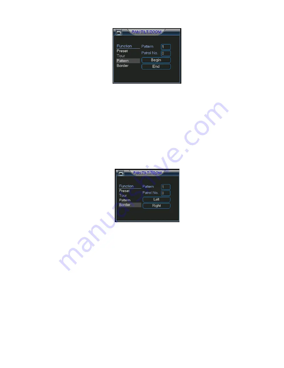
Figure 4-37
4.9.6 Activate Pattern Function
In Figure 4-34, input the desired pattern preset value in the No. field and click pattern
to activate it.
4.9.7 Auto Scan Setup
In Figure 4-33, click border button. You can see an interface is shown as in Figure
4-28.
Go to Figure 4-30. Use the directional arrows to select the camera’s left limit.
Then please go to Figure 4-38 and click left limit.
Repeat the above procedures to set the right limit.
Figure 4-38
4.9.8 Activate Auto Scan
In Figure 4-34 click Auto Scan to begin the auto scan. Click stop to end the scan.
Correspondingly, the auto scan button becomes to stop button. Click stop button to
terminate scan operation.
4.10
4.10
4.10
4.10
Flip
Flip
Flip
Flip
In Figure 4-34, click page switch button, you can see an interface is shown as below.
See
Figure 4-39. Here you can set auxiliary function.
Click page switch button again, system goes back to Figure 4-30.
Summary of Contents for Max 16
Page 1: ... 2009 IC Realtime Inc 1 Standalone DVR User s Manual Max 8 16 ...
Page 29: ... 2009 IC Realtime Inc 29 Figure 3 11 ...
Page 47: ... 2009 IC Realtime Inc 47 Figure 4 21 Figure 4 22 Figure 4 23 Figure 4 24 ...
Page 55: ... 2009 IC Realtime Inc 55 Figure 4 39 ...
Page 111: ... 2009 IC Realtime Inc 111 Figure 7 38 Figure 7 39 ...
Page 112: ... 2009 IC Realtime Inc 112 Figure 7 40 Figure 7 41 Figure 7 42 ...
Page 128: ... 2009 IC Realtime Inc 128 ...
Page 140: ... 2009 IC Realtime Inc 140 ...


