©2009 IC Realtime, Inc.
129
8.3
8.3
8.3
8.3
Viewing Live Cameras
Viewing Live Cameras
Viewing Live Cameras
Viewing Live Cameras
After successfully creating a new connection for the DVR, select the device and then
click connect/disconnect button
(
)
.
Select the channel you wan to view, click connect/disconnect,
(
)
again.
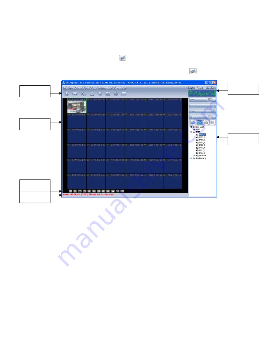
Figure 8-3
There are total six sections:
Section 1: There are eight function keys: monitor, E-map, record, save, alarm,
configuration, log and system.
Section 2: This is where you can view channel video.
Section 3: This is where you can select display mode. System supports various
display modes. HD item is for you to select priority between network latency and
video fluency.
Section 4: This is where you can view current help information.
Section 5: Here is the display for data flux and CPU status.
Section 6: There are four function buttons: PTZ, color, device, and plan. For
best performance, we recommend resolution 1024*768.
Select a device name and then click connect/disconnect, you will connect to the
current selected DVR. You will notice the red-cross below the name disappeared.
Select a window on you left side (Section-2) and then double click the channel name
on you right hand (Section-6), you will notice the corresponding video in the
highlighted window.
Please refer to Figure 8-4 for connection/disconnection information.
Section 1
Section 2
Section 3
Section 4
Section 5
Section 6
Summary of Contents for Max 16
Page 1: ... 2009 IC Realtime Inc 1 Standalone DVR User s Manual Max 8 16 ...
Page 29: ... 2009 IC Realtime Inc 29 Figure 3 11 ...
Page 47: ... 2009 IC Realtime Inc 47 Figure 4 21 Figure 4 22 Figure 4 23 Figure 4 24 ...
Page 55: ... 2009 IC Realtime Inc 55 Figure 4 39 ...
Page 111: ... 2009 IC Realtime Inc 111 Figure 7 38 Figure 7 39 ...
Page 112: ... 2009 IC Realtime Inc 112 Figure 7 40 Figure 7 41 Figure 7 42 ...
Page 128: ... 2009 IC Realtime Inc 128 ...
Page 140: ... 2009 IC Realtime Inc 140 ...


