©2009 IC Realtime, Inc.
23
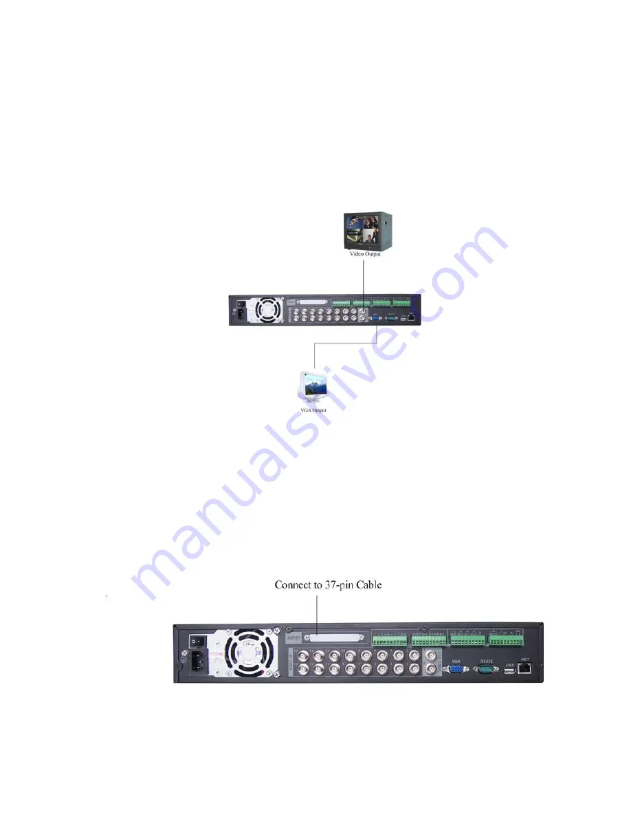
This section provides information about physically connecting video display devices
to the DVR. See Figure 3-2.
If you connect the DVR with a TV monitor or VGA monitor, the DVR can automatically
detect the monitor type. Without any output device, by default, the DVR is configured
to use a TV monitor. If your application requires a VGA monitor, you have to press
“
FN2
”
or Shift on the front panel.
NOTE:
Video output 1 and VGA can
’
t display at the same time. But Video output 2 can
display properly with Video Output 1 or VGA.
Figure 3-2
3.7
3.7
3.7
3.7
C
C
C
Connecting
onnecting
onnecting
onnecting Audio Input
Audio Input
Audio Input
Audio Input &
&
&
& Output
Output
Output
Output, Bidirectional Audio, Looping
, Bidirectional Audio, Looping
, Bidirectional Audio, Looping
, Bidirectional Audio, Looping
Video, Matrix
Video, Matrix
Video, Matrix
Video, Matrix
For the 25-pin or 37-pin interface, different models include different functions.
For example, our 16-ch audio/video basic model has 16 audio inputs, 1 audio output,
1 bidirectional audio input. See Figure 3-3.
Figure 3-3
3.7.1 Audio Input/Audio Output
Summary of Contents for Max 16
Page 1: ... 2009 IC Realtime Inc 1 Standalone DVR User s Manual Max 8 16 ...
Page 29: ... 2009 IC Realtime Inc 29 Figure 3 11 ...
Page 47: ... 2009 IC Realtime Inc 47 Figure 4 21 Figure 4 22 Figure 4 23 Figure 4 24 ...
Page 55: ... 2009 IC Realtime Inc 55 Figure 4 39 ...
Page 111: ... 2009 IC Realtime Inc 111 Figure 7 38 Figure 7 39 ...
Page 112: ... 2009 IC Realtime Inc 112 Figure 7 40 Figure 7 41 Figure 7 42 ...
Page 128: ... 2009 IC Realtime Inc 128 ...
Page 140: ... 2009 IC Realtime Inc 140 ...


