Chapter 3 Operation
3.5 Input and Output Signal Process for Field Network
119
3.5 Input and Output Signal Process for Field Network
(1) I/O Signal Timings
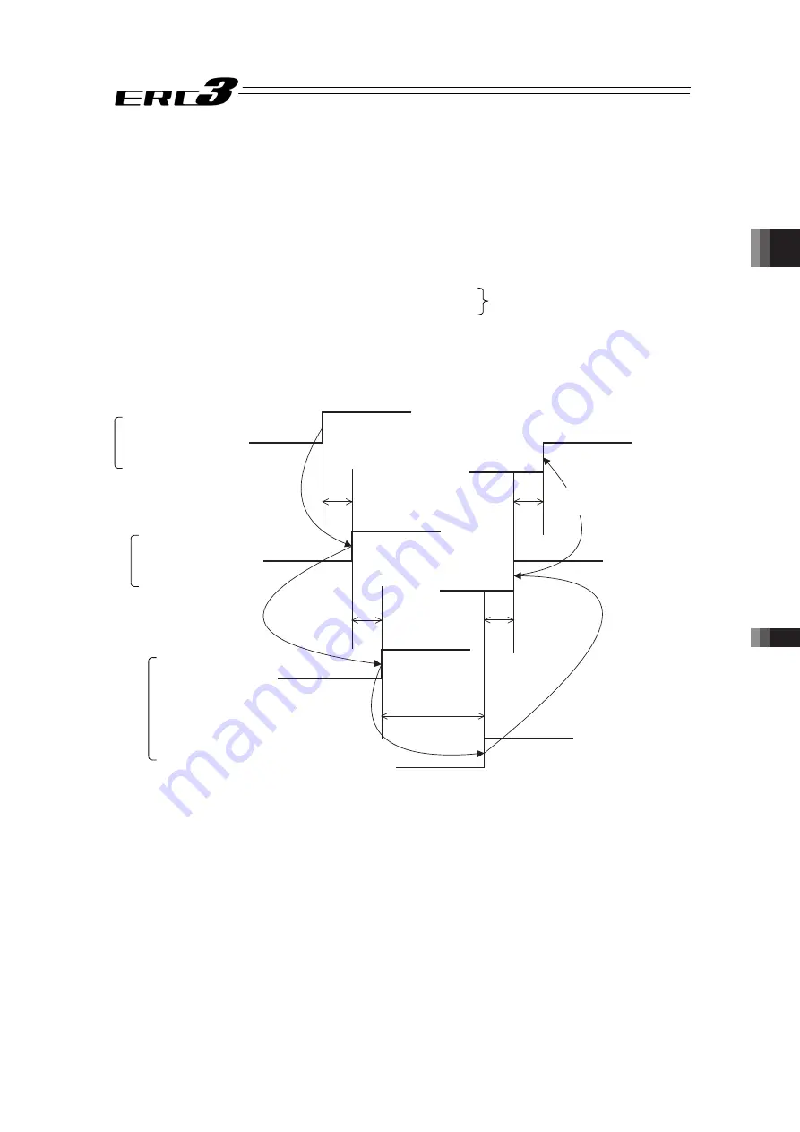
When any of the control signal is turned ON to perform the operation of the ERC3 using the
PLC’s sequence program, the response (status) is returned to the PLC. The maximum
response time is expressed using the following formula.
The value is constant regardless the number of composition axes.
Max. response time (msec) = Yt + Xt + 20 + Response process time (operation time, etc.)
Yt : Master Station → Slave Transmission Delay Time
Xt : Slave → Master Station Transmission Delay Time
Refer to the instruction manual of the mounted PLC for the master station → slave transfer
delay time (Yt) and the slave → master station transfer delay time (Xt).
Response Process
Time *
2
PLC Sequence Program
Control Signal
Status Signal
Gateway
Control Signal
Status Signal
Controller
Control Signal
Status Signal
*1 Refer to PLC Manual
*2 Varies depending on the content of control
10ms
10ms
Remote I/O Station → Master
Transmission Delay Time (Xt) *1
Master → Remote I/O Station
Transmission Delay Time (Yt) *1
Field Network Transmission Delay Time
ME0302-4A
Summary of Contents for ERC3
Page 1: ...IAI Corporation ERC3 Gateway Unit Instruction Manual Forth Edition ...
Page 2: ......
Page 4: ...ME0302 4A ...
Page 8: ...ME0302 4A ...
Page 35: ...Chapter 1 Specifications Check 1 6 Option 27 1 6 Option はケーブル長 ME0302 4A ...
Page 54: ...Chapter 2 Wiring 2 3 Wiring Method 46 ME0302 4A ...
Page 158: ...Chapter 3 Operation 3 8 Field Network LED Indication 150 ME0302 4A ...
Page 160: ...Chapter 4 I O Parameter 152 ME0302 4A ...
Page 176: ...Chapter 5 Troubleshooting 5 4 Alarm List 168 ME0302 4A ...
Page 186: ......
Page 187: ......


