112
,,
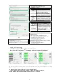
• Select the load movement inertia mark
0: No estimation of moving inertia [factory setting]
1. Estimated moment of inertia
Selection pattern
Selection
pattern
Description
1: Standard
Make standard gain adjustments. In addition to
gain adjustment, notch filter and Type A vibration
suppression are automatically adjusted.
2: Location
Make special adjustment for positioning purpose.
In addition to gain adjustment, model tracking
control, notch filter, type A vibration suppression
and vibration suppression are also automatically
adjusted.
3: Location
(Pay attention
not to
overshoot)
In the positioning application, it is necessary to
pay attention to the adjustment without overshoot.
In addition to gain adjustment, notch filter, type A
vibration suppression and vibration suppression
are automatically adjusted.
• Institutional choice
Institutional choice
Description
1. Belt transmission
mechanism
Adjustments
suitable
for
less
rigid
mechanisms such as belt mechanisms are
made.
2.
Ball
screw
mechanism or linear
servo mechanism
The adjustment is suitable for high rigidity
mechanisms
such
as
ball
screw
mechanisms or linear servo motors. Please
select this type when there is no
corresponding organization.
3.
Rigid
body
mechanism
Adjust the mechanism with higher rigidity
such as rigid body system.
• Distance
Set the moving distance.
Movement Range:-99990000 ~+99990000 [Command Unit]
Minimum setting scale for moving distance: 1000 [command unit]
Initial settings value:
The rotary servo motor rotates about 3 times.
Directly drive the servo motor for about 0.3 coils
Linear servo motor approx. 90mm
Please set the value above the following value. In addition, in order to
ensure the adjustment accuracy, it is recommended to set the moving
distance around the initial set value.
The rotary servo motor rotates 0.5 coils.
Directly drive the servo motor for 0.05 coils
Linear servo motor 5mm
• Tuning parameters
Specify the adjustment parameters to use.
If the [Start Tuning with Default] check box is checked, the
adjustment will be performed after the adjustment parameters
return to the factory state.
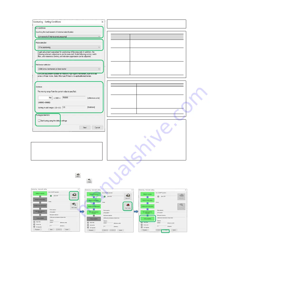
6. Enter the [Auto Tuning] window
Click the [Servo On] button (
icon) to energize the servo motor.
Next, click the [Start Tuning] button (
icon) to rotate the servo motor and perform adjustment.
The vibration generated in the adjustment is automatically detected and the generated vibration is optimally
set.
The executed function frame will light up after the setting is completed
7. Click the [Finish] button to return to the [Tuning Axis] window after tuning is completed.
Then, the operation of automatic adjustment (no upper command) is completed.
Figure 8

