111
The following describes the adjustment of automatic adjustment (no upper command).
• The automatic adjustment (without a bit command) is based on the set speed loop gain (Pn100). If vibration
occurs at the beginning of the adjustment, the correct adjustment cannot be made. Please reduce the speed
loop gain (Pn100) until it stops vibrating and adjust.
• When the adjustment-free function is valid (Pn170 = n.
1 [factory setting]), automatic adjustment (no
upper command) cannot be performed. Please set the adjustment-free function to invalid (Pn170 = n.
0) and adjust.
• After performing the automatic adjustment (without the upper command), change the load state of the
machine or the transmission mechanism, etc. When setting the "Estimated Moment of Inertia" again to
perform the automatic adjustment (without the upper command), please set the following parameters. If the
automatic adjustment is performed in a state other than the following (no upper command), mechanical
vibration and mechanical damage may be caused.
Pn140 = n.
0 (without model tracking control)
Pn160 = n.
0 (type a vibration suppression control is not used)
Pn408=n.00
0 (no friction compensation, 1st and 2nd notch filters used)
(Note) If the above parameters are not displayed when using the digital operator, please select the
settings (PN00B = n.
1) to display all parameters and switch on the power again.
■ Confirmation before execution
Be sure to confirm the following settings before performing the automatic adjustment (no upper command).
• The main circuit power supply must be ON.
• No over-travel is allowed.
• Must be in servo OFF state.
• Not for torque control.
• The gain switch selection switch must be manual gain switch (Pn139 = n.
0).
• Gain 1 must have been selected.
• No motor test function selection must be invalid (Pn00C = n.
0).
• No alarm or warning shall be generated.
• Hardware Base Blocking (HWBB) function must be invalid.
• The write inhibit setting of the parameter must not be set to "write inhibit"
• The adjustment-free function must be set to invalid (Pn170=n.
0) or "estimated moment of inertia"
when the adjustment-free function is set to valid (Pn170 = n.
1)
• The mode selection must be set to 1 when executing in the state of speed control
Operating Steps
1. Confirm that the rotational inertia ratio (Pn103) has been correctly set.
2. Connect the servo driver and click the "Tune" button in the working area of the [System Detection]
window (Figure 5).
Or click the tune shortcut button (icon) from the shortcut menu of the []
debug window.
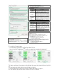
3. Enter the [Tuning] window and click the [Execute] button (Figure 6).
4. Enter the [Tuning Axis] window (Figure 7)
Select the [Auto Tuning] group
Select [No Reference Input]
Click the [Auto Tuning] button
5. Enter the [Auto Tuning Setting Conditions] window (Figure 8)
Set separately
• [Select Load Moving Inertia Marker] Column
• [Mode Selection] Column
• [Institutional choice] column
• [Distance] column
• [Tuning Parameters] column
Then click [Next]
Figure 5
Figure 6
Figure 7


