72
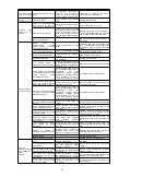
Alarm number:
Alarm name
Reason
Confirmation method
The treatment measures
A.0b0
:
Servo ON command is
invalid alarm
After performing the auxiliary function of
energizing the motor, servo is sent from
the upper device ON(SV_ON) command
-
Connect to the servo drive power supply
again. Or perform a software reset.
A.100
:
Overcurrent detection
(overcurrent flows
through the power
transistor or heat sink to
overheat)
The main loop cable is incorrectly wired
or has poor contact.
Verify that the wiring is correct.
Modify the wiring.
Internal short circuit of main loop cable or
short circuit to ground occurred.
Verify that there is a short circuit between
UVW phases of the cable and between
UVW and ground.
The cable may be short-circuited. Replace the
cable.
Short circuit or short circuit to ground
occurs inside servo motor
Verify that there is a short circuit between
UVW phases of the motor terminals and
between UVW and ground.
It is possible that the servo motor is faulty.
Replace the servo motor.
Incorrect wiring or poor contact of
regenerative resistor
Verify that the wiring is correct.
Modify the wiring.
The dynamic brake (emergency stop due
to DB and servo drive) is used frequently
or DB overload alarm occurs.
Use frequency of DB is confirmed by power
consumption of DB resistor. Or use alarm
display to confirm whether DB overload
alarm has occurred (A.730 or A.731).
Change the type selection, operation method
and mechanism of servo drive to reduce the
use frequency of DB.
Regenerative resistance value is too
high
Confirm the frequency of use of the
regenerative resistor.
Discuss the operating conditions and loads
again.
The regenerative resistance value of
servo drive is too small
Confirm the frequency of use of the
regenerative resistor.
The regenerative resistance value is changed
to a value above the minimum allowable
resistance value for servo drive.
When the servo motor stops or runs at
low speed, it bears high load
Verify that the operating conditions are
outside the specifications of the servo drive.
Reduce the load borne by the servo motor. Or
at a higher operating speed.
Misoperation due to interference
Improve the interference environment such
as wiring and confirm whether there is any
effect.
Take measures to prevent interference, such
as correctly wiring FG. In addition, the wire
size of FG should be the same as that of servo
drive main loop.
Servo drive failure
-
Connect to the servo drive power supply
again. When an alarm still occurs, replace the
servo drive.
A.101
:
Motor overcurrent
detection
(The motor flows
through excess
capacity
Allowable current)
The main loop cable is incorrectly wired
or has poor contact
Verify that the wiring is correct
Modify the wiring.
Internal short circuit of main loop cable or
short circuit to ground occurred
Verify that there is a short circuit between
UVW phases of the cable and between
UVW and ground.
The cable may be short-circuited. Replace the
cable.
Short circuit or short circuit to ground
occurs inside servo motor
Verify that there is a short circuit between
UVW phases of the motor terminals and
between UVW and ground.
It is possible that the servo motor is faulty.
Replace the servo motor.
Short circuit or short circuit to ground
occurred inside servo drive
Verify that there is a short circuit between
UVW phases and between UVW and
ground at the servo motor connection
terminal of servo drive.
Replace the servo drive.
When the servo motor stops or runs at
low speed, it bears high load
Verify that the operating conditions are
outside the specifications of the servo drive.
Reduce the load borne by the servo motor. Or
at a higher operating speed.
Misoperation due to noise
Improve the noise environment such as
wiring and setting, and confirm whether
there is any effect.
Take anti-interference measures, such as
correctly wiring FG, etc. In addition, the wire
size of FG should be the same as that of servo
drive main loop.
Servo drive failure
-
Connect to the servo drive power supply
again. When an alarm still occurs, replace the
servo drive
A.300
:
Regenerative faults
The regenerative resistance capacity
(Pn600) is set to a value other than "0",
and no regenerative resistance is
installed
Confirm the connection of external
regenerative resistor and the value of
Pn600.
Connect external regenerative resistor or set
Pn600 (regenerative resistor capacity) to 0
when regenerative resistor is not needed.
No external regenerative resistance
Confirm external regenerative resistor or
regenerative power resistance device
connection and Pn600 value.
Set the appropriate value for Pn600 after
connecting the external regenerative resistor,
or set Pn600 to 0 after connecting the
regenerative resistor device.
The jumper wire of the regenerative
resistor connection terminal B2-B3 falls
off
Confirm the wiring of the power terminal
jumper.
Correct wiring of jumper wires.
Poor
connection,
falling
off
or
disconnection of external regenerative
resistor
Confirm the wiring of the external
regeneration resistor.
Correct wiring of external regenerative
resistor.
Servo drive failure
-
In the state that the main loop power supply is
not turned on, the servo drive control power
supply is turned on again. When an alarm still
occurs, replace the servo drive.
A.320
:
Regeneration overload
Power
supply
voltage
exceeds
specification range
Measure the supply voltage.
Set the power supply voltage within the
specification.
External regenerative resistance value or
regenerative resistance capacity is
insufficient or in continuous regenerative
state
Reconfirm
operating
conditions
and
capacity.
Change the regenerative resistance value and
regenerative resistance capacity. Adjust the
operating conditions again.
Continuously bears negative load and is
in continuous regeneration state
Confirm the load applied to the running
servo motor.
Discuss
the
system
including
servo,
mechanical and operating conditions again.
The capacity set in Pn600 (regenerative
resistance capacity) is smaller than the
capacity
of
external
regenerative
resistance
Confirm the connection of regenerative
resistor and the value of Pn600.
Correct the Pn600 setting.
The value set in Pn603 (regenerative
resistance value) is smaller than the
external regenerative resistance value
Confirm the connection of regenerative
resistor and the value of Pn603.
Correct the Pn603 setting.
Excessive
external
regenerative
resistance
Verify that the regenerative resistance
value is correct.
Change it to the correct resistance value and
capacity
Servo drive failure
-
Replace the servo drive.
A.330
:
Main
circuit
power
supply
wiring
error
(detected when main
circuit power is turned
on)
The power supply voltage inside the
servo drive is too high, and the
regenerative resistor is disconnected.
Measure the resistance value of the
regenerative resistor with a measuring
instrument.
Replace the servo drive when using the
regenerative resistor built into the servo drive.
When using an external regenerative resistor,
replace the regenerative resistor.
When setting AC power input, DC power
is input
Verify that the power supply is DC.
Make the set value of the power supply
consistent with the power supply used.
When setting DC power input, AC power
is input
Verify that the power supply is AC.
Make the set value of the power supply
consistent with the power supply used.
The regenerative resistance capacity
(Pn600) is set to a value other than "0"
and no regenerative resistance is
installed
Confirm the connection of external
regenerative resistor and the value of
Pn600.
Connect an external regenerative resistor or
set Pn600 to 0 when no external regenerative
resistor is required.
Servo drive failure
-
Replace the servo drive.


