15
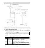
sequence control. Switch on the main circuit power
supply after ALM signal OFF (alarm cleared).
△
!
Warning
Even if the power supply is turned off, high voltage may remain in the servo drive. To prevent electric shock, do
not touch the power terminals. After the discharge is completed, the CHARGE indicator will go out. Please
connect and check after confirming that the CHARGE indicator is off.
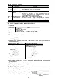
4.3.4 Power wiring diagram
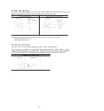
Example of wiring for three-phase power input:
* HSD7-24D
, HSD7-35D
No built-in resistor, no short circuit between B2 and B3. Please do not short-circuit.
4.3.5 Connection of Regenerative Resistance
The connection of the external regenerative resistor will be described below.
△
!
Warning
Do not mistake the wiring of the regenerative resistor. In particular, do not short-circuit B1/
⊕
-B2.
Otherwise, the regenerative resistor and servo drive will be damaged and fire will occur.
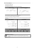
Connection method of regenerative resistor
1. Remove the wire between terminals B2-B3 of servo drive
2. Connect external regenerative resistor to B1/
⊗
and B2 terminals.
3. Set Pn600 (regenerative resistance capacity) and Pn603 (regenerative resistance value).
(Note) HSD7-24D
and HSD7-35D
no built-in regenerative resistor, and cannot be shorted between B2 and B3.
External regenerative resistor shall be connected between B1/
⊗
and B2.
Servo unit
(For servo alarm
display)
Servo
power on
Servo
power off
1QF: circuit breaker for wiring
1FLT: noise filter
1KM: electromagnetic contactor (for
controlling power supply)
2KM: electromagnetic contactor (for
main circuit power supply)
1Ry: relay
1PL: Indicator for Display
1SA: Surge Absorber
2SA: Surge absorber
3SA: Surge Absorber
1D: Bypass Diode


