


Chapter 4 Explanation of Functions
4 - 19
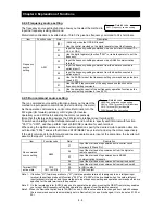
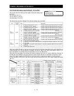
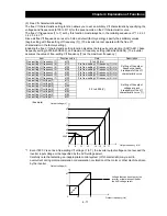
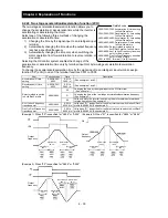
(2) Automatic torque boost
When automatic torque boost (data "01") is selected by the torque boost selection (A041/A241), the
inverter automatically adjusts the output frequency and voltage according to the load on the motor.
(During actual operation, the automatic torque boost is usually combined with the manual torque boost.)
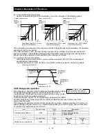
When you select the automatic torque boost, adjust the settings of the motor capacity selection
(H003/H203) and motor pole selection (H004/H204) according to the motor to be driven.
If the inverter trips due to overcurrent during motor deceleration, set the AVR function select (A081) to
always enable the AVR function (data "00").
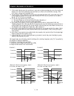
If you cannot obtain the desired operation characteristic by using the automatic torque boost, make the
following adjustments:
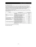
Symptom Adjustment
method Adjustment
item
Motor torque is insufficient at low
speed.
(The motor does not rotate at low
speed.)
(1) Increase the voltage setting for manual torque boost
step by step.
A042/A242
(2) Increase the slippage compensation gain for
automatic torque boost step by step.
A047/A247
(3) Increase the voltage compensation gain for
automatic torque boost step by step.
A046/A246
(4) Reduce the carrier frequency setting.
b083
The motor speed falls when a load
is applied to the motor.
Increase the slippage compensation gain for the
automatic torque boost step by step.
A047/A247
The motor speed increases when a
load is applied to the motor.
Reduce the slippage compensation gain for the
automatic torque boost step by step.
A047/A247
The inverter trips due to overcurrent
when a load is applied to the motor.
(1) Reduce the voltage compensation gain for the
automatic torque boost step by step.
A046/A246
(2) Reduce the slippage compensation gain for the
automatic torque boost step by step.
A047/A247
(3) Reduce the voltage setting for the manual torque
boost step by step.
A042/A242
This function cannot be selection for 3rd moter setting.
Manual torque boost valid.
Summary of Contents for L700 Series
Page 16: ... Memo ...
Page 20: ... Memo ...
Page 22: ... Memo ...
Page 46: ... Memo ...
Page 60: ... Memo ...
Page 62: ... Memo ...
Page 212: ... Memo ...
Page 222: ... Memo ...
Page 224: ... Memo ...
Page 232: ... Memo ...
Page 238: ...Chapter 7 Specifications 7 6 L700 750 LFF 6 Cable hole φ41 ...
Page 239: ...Chapter 7 Specifications 7 7 L700 900 to 1100HFF L700 1320 to 1600HFF ...
Page 240: ... Memo ...
Page 242: ... Memo ...
Page 258: ... Memo ...