


Chapter 4 Explanation of Functions
4 - 12
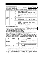
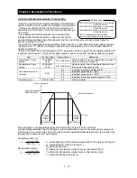
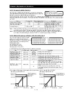
4.2.11 External analog input setting (O, OI, and O2)
The inverter has the following three types of external analog input
terminals:
O-L terminal: 0 to 10 V
OI-L terminal: 4 to 20 mA
O2-L terminal: -10 to 10 V
The table below lists the settings of the external analog input terminals.
Item
Function
code
Data Description
[AT]
selection
A005
00
Switching between the O and OI
terminals with the AT terminal
Turning on the AT terminal enables the OI-L terminal.
Turning on the AT terminal enables the O-L terminal.
01
Switching between the O and O2
terminals with the AT terminal
Turning on the AT terminal enables the O2-L terminal.
Turning on the AT terminal enables the O-L terminal.
(02)
(Valid only when the OPE-SR is used)
Switching between the O terminal and
the control with the AT terminal
Turning on the AT terminal enables the pot on
OPE-SR terminal.
Turning on the AT terminal enables the O-L terminal.
(03)
(Valid only when the OPE-SR is used)
Switching between the OI terminal and
the control with the AT terminal
Turning on the AT terminal enables the pot on
OPE-SR terminal.
Turning on the AT terminal enables the OI-L terminal.
(04)
(Valid only when the OPE-SR is used)
Switching between the O2 terminal
and the control with the AT terminal
Turning on the AT terminal enables the pot on
OPE-SR terminal.
Turning on the AT terminal enables the O2-L terminal.
[O2]
selection
A006
00
Using the O2 terminal independently
01
Using the O2 terminal for auxiliary frequency command (nonreversible) in addition to the O and
OI terminals
02
Using the O2 terminal for auxiliary frequency command (reversible) in addition to the O and OI
terminals
03
Disabling the O2 terminal
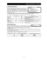
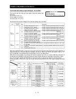
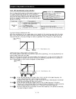
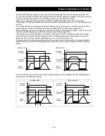
Note that whether frequency commands are input to the O2-L terminal and whether the motor operation is
reversible depend on the combination of settings of functions "A005" and "A006" and whether function "16"
(AT) is assigned to an intelligent input terminal as shown in the table below.
When the motor operation is reversible, the inverter operates the motor in a reverse direction if the sum of
the frequencies specified by the main frequency and auxiliary frequency commands is less than 0 (even
when the forward operation [FW] terminal is on). Even when no wire is connected to the 02 terminal,
reverse operation of the motor may occur and prolong the acceleration time if the output voltage fluctuates
near 0 V.
A006
A005
AT
terminal
Main frequency command
Whether to input an auxiliary
frequency command
(via the O2-L terminal)
Reversible/
nonreversible
When the AT
function is
assigned to an
intelligent input
terminal
00,03
00
OFF
O-L terminal
No input
Nonreversible
ON
OI-L terminal
No input
01
OFF
O-L terminal
No input
ON
O2-L terminal
No input
Reversible
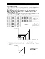
01
00
(Example 1)
OFF O-L
terminal
Input
Nonreversible
ON OI-L
terminal
Input
01
OFF O-L
terminal
Input
ON
O2-L terminal
No input
Reversible
02
00
(Example 2)
OFF O-L
terminal
Input
Reversible
ON OI-L
terminal
Input
01
OFF O-L
terminal
Input
ON
O2-L terminal
No input
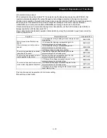
When the AT
function is not
assigned to any
intelligent input
terminal
00
-
-
O2-L terminal
No input
Reversible
01
-
-
Addition of signals on O-L and
OI-L terminals
Input Nonreversible
02
-
-
Addition of signals on O-L and
OI-L terminals
Input Reversible
03
-
-
Addition of signals on O-L and
OI-L terminals
No input
Nonreversible
A005: [AT] selection
A006: [O2] selection
C001 to C008: Terminal [1] to [8] functions
Related code
Summary of Contents for L700 Series
Page 16: ... Memo ...
Page 20: ... Memo ...
Page 22: ... Memo ...
Page 46: ... Memo ...
Page 60: ... Memo ...
Page 62: ... Memo ...
Page 212: ... Memo ...
Page 222: ... Memo ...
Page 224: ... Memo ...
Page 232: ... Memo ...
Page 238: ...Chapter 7 Specifications 7 6 L700 750 LFF 6 Cable hole φ41 ...
Page 239: ...Chapter 7 Specifications 7 7 L700 900 to 1100HFF L700 1320 to 1600HFF ...
Page 240: ... Memo ...
Page 242: ... Memo ...
Page 258: ... Memo ...