

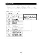


Chapter 3 Operation
3 - 2
You can operate the inverter in different ways, depending on how to input the operation and
frequency-setting commands as described below.
This section describes the features of operating methods and the items required for operation.
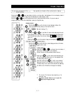
(1) Entering operation and frequency-setting commands from the digital operator
This operating method allows you to operate the inverter through key operations on the standard
digital operator mounted in the inverter or an optional digital operator.
When operating the inverter with a digital operator alone, you need not wire the control circuit
terminals.
(Items required for operation)
1) Optional digital operator (not required when you use the standard digital operator)
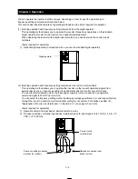
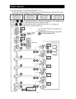
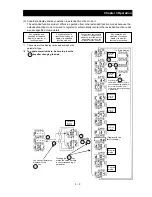
(2) Entering operation and frequency-setting commands via control circuit terminals
This operating method allows you to operate the inverter via the input of operation signals from
external devices (e.g., frequency-setting circuit and start switch) to control circuit terminals.
The inverter starts operation when the input power supply is turned on and then an operation
command signal (FW or RV) is turned on.
You can select the frequency-setting method (setting by voltage specification or current specification)
through the input to a control circuit terminal according to your system. For details, see Item (2),
"Explanation of control circuit terminals," in Section 2.2.1 (on pages 2-7 and 2-8).
(Items required for operation)
1) Operation command input device: External switch or relay
2) Frequency-setting command input device: External device to input signals (0 to 10 VDC, -10 to +10
VDC, or 4 to 20 mA)
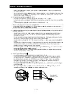
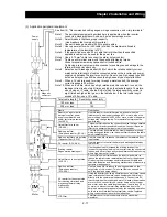
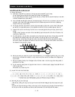
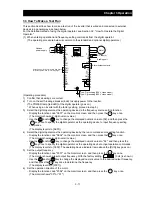
Digital operator
Operation command input
device (switch)
Frequency-setting command
input device (control)
Control circuit
terminal block
H
O L
FW
Summary of Contents for L700 Series
Page 16: ... Memo ...
Page 20: ... Memo ...
Page 22: ... Memo ...
Page 46: ... Memo ...
Page 60: ... Memo ...
Page 62: ... Memo ...
Page 212: ... Memo ...
Page 222: ... Memo ...
Page 224: ... Memo ...
Page 232: ... Memo ...
Page 238: ...Chapter 7 Specifications 7 6 L700 750 LFF 6 Cable hole φ41 ...
Page 239: ...Chapter 7 Specifications 7 7 L700 900 to 1100HFF L700 1320 to 1600HFF ...
Page 240: ... Memo ...
Page 242: ... Memo ...
Page 258: ... Memo ...