


Chapter 2 Installation and Wiring
2 - 9
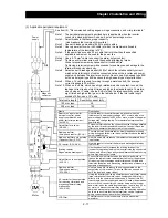
Symbol Terminal name
Description
Electric property
Dig
ita
l (co
nt
a
ct)
Cont
ac
t in
put
Function
selecti
o
n
and l
o
gic switchin
g
PLC
Intelligent input
(common)
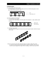
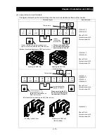
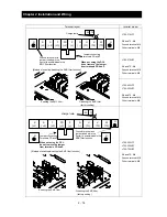
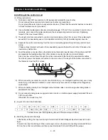
To switch the control logic between sink logic and source logic, change the
jumper connection of this (PLC) terminal to another terminal on the control
circuit terminal block.
Jumper terminals P24 and PLC for the sink logic; jumper terminals CM1
and PLC for the sink logic.
To use an external power supply to drive the contact inputs, remove the
jumper, and connect the PLC terminal to the external interface circuit.
Open colle
ctor
ou
tp
ut
S
tatu
s and
factor
11
12
13
14
15
Intelligent output
Select five of a total 51 functions, and assign these five functions to
terminals 11 to 15.
If you have selected an alarm code using the function "C062", terminals 11
to 13 or 11 to 14 are used exclusively for the output of cause code for alarm
(e.g., inverter trip). The control logic between each of these terminals and
the CM2 terminal always follows the sink or source logic.
Voltage drop between each
terminal and CM2 when
output signal is on: 4 V or
less
Maximum allowable
voltage: 27 VDC
Maximum allowable
current: 50 mA
CM2
Intelligent output
(common)
This terminal serves as the common terminal for intelligent output terminals
[11] to [15].
Rela
y cont
act outp
ut
S
tatu
s and
alarm
AL0
AL1
AL2
Intelligent relay
output
Select functions from the 43 available, and assign the selected functions to
these terminals, which serve as C contact output terminals.
In the initial setting, these terminals output an alarm indicating that the
inverter protection function has operated to stop inverter output.
(Maximum contact
capacity)
AL1-AL0: 250 VAC, 2 A
(resistance) or 0.2 A
(inductive load)
AL2-AL0: 250 VAC, 1 A
(resistance) or 0.2 A
(inductive load)
(Minimum contact capacity)
100 VAC, 10 mA
5 VDC, 100 mA
Analog
Analog i
nput
Sensor
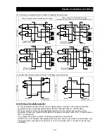
TH
External
thermistor input
Connect to an external thermistor to make the inverter trip if an abnormal
temperature is detected.
The CM1 terminal serves as the common terminal for this terminal.
[Recommended thermistor properties]
Allowable rated power: 100 mW or more
Impedance at temperature error: 3k
Ω
The impedance to detect temperature errors can be adjusted within the
range 0
Ω
to 9,999
Ω
.
Allowable range of input
voltages
0 to 8 VDC
[Input circuit]
DC8V
10k
Ω
1k
Ω
CM1
TH
Thermistor
Summary of Contents for L700 Series
Page 16: ... Memo ...
Page 20: ... Memo ...
Page 22: ... Memo ...
Page 46: ... Memo ...
Page 60: ... Memo ...
Page 62: ... Memo ...
Page 212: ... Memo ...
Page 222: ... Memo ...
Page 224: ... Memo ...
Page 232: ... Memo ...
Page 238: ...Chapter 7 Specifications 7 6 L700 750 LFF 6 Cable hole φ41 ...
Page 239: ...Chapter 7 Specifications 7 7 L700 900 to 1100HFF L700 1320 to 1600HFF ...
Page 240: ... Memo ...
Page 242: ... Memo ...
Page 258: ... Memo ...