


Chapter 3 Operation
3 - 13
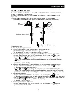
(Operating procedure)
1) Confirm that all wirings are correct.
2) Turn on the earth-leakage breaker (ELB) to supply power to the inverter.
(The POWER lamp [red LED] of the digital operator goes on.)
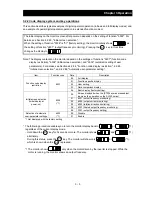
3) Select the control circuit terminal block as the device to input frequency-setting commands by the
frequency source setting function.
- Display the function code "A001" on the monitor screen, and then press the key once.
(The monitor shows a 2-digit numeric value.)
- Use the and/or key to change the displayed numeric value to [01], and then press the
key once to specify the control circuit terminal block as the device to input frequency-setting
commands.
(The display reverts to [A001].)
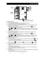
4) Select the control circuit terminal block as the device to input operation commands by the run
command source setting function.
- Display the function code "A002" on the monitor screen, and then press the key once.
(The monitor shows a 2-digit numeric value.)
- Use the and/or key to change the displayed numeric value to "01", and then press the
key once to specify the digital operator as the device to input operation commands.
(The display reverts to [A002].)
5) Set the monitor mode.
- To monitor the output frequency, display the function code "d001", and then press the key once.
(The monitor shows the output frequency.)
To monitor the operation direction, display the function code "d003", and then press the key
once.
(The monitor shows for forward operation, for reverse operation, or for stopping.)
6) Start the motor operation.
- Set the FW signal (at the FW terminal on the control terminal block) to the ON level to start the
motor.
(The RUN lamp [green LED] goes on.)
- Apply a voltage across the terminals O and L on the control circuit block to output the frequency
corresponding to the applied voltage from the inverter.
7) Stop the motor.
- Set the FW signal (at the FW terminal on the control terminal block) to the OFF level to decelerate
and stop the motor.
(When the motor stops, the RUN lamp [green LED] goes off.)
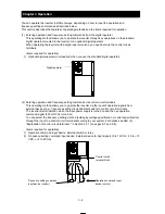
U
V
W
PD
P
RB
N
AL0
AL1
AL2
11
・ ・
・ ・
CM2
15
SP
SN
RP
SN
G
H
L
O
H
Operating box
(OPE-4MJ2)
(OPE-8MJ2)
AMI
AM
L
O2
OI
O
P24
PLC
CM1
TH
FM
1
8
FW
R
S
T
R
S
T
ELB
(RV)
Type-D grounding (200 V class model)
Type-C grounding (400 V class model)
DC reactor
Motor
Braking unit
3-phase
power supply
Digital operator
FUNC
1
2
FUNC
1
2
STR
STR
FUNC
FUNC
Default: for sinking type
Summary of Contents for L700 Series
Page 16: ... Memo ...
Page 20: ... Memo ...
Page 22: ... Memo ...
Page 46: ... Memo ...
Page 60: ... Memo ...
Page 62: ... Memo ...
Page 212: ... Memo ...
Page 222: ... Memo ...
Page 224: ... Memo ...
Page 232: ... Memo ...
Page 238: ...Chapter 7 Specifications 7 6 L700 750 LFF 6 Cable hole φ41 ...
Page 239: ...Chapter 7 Specifications 7 7 L700 900 to 1100HFF L700 1320 to 1600HFF ...
Page 240: ... Memo ...
Page 242: ... Memo ...
Page 258: ... Memo ...