


Chapter 4 Explanation of Functions
4 - 48
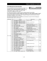
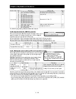
Function code
Data
Description
Reference item
Page
C001 to C008
51 F-TM:
Forcible-terminal
operation
Forcible-terminal operation function
4-52
53
KHC: Cumulative power clearance
Cumulative power monitoring function
4-4
55
FOC: Forcing
forcing function
4-92
56
MI1: General-purpose input 1
Easy sequence function (*1)
-
57
MI2: General-purpose input 2
58
MI3: General-purpose input 3
59
MI4: General-purpose input 4
60
MI5: General-purpose input 5
61
MI6: General-purpose input 6
62
MI7: General-purpose input 7
63
MI8: General-purpose input 8
65
AHD: Analog command holding
Analog command holding function
4-61
74
PCNT: Pulse counter
Intelligent pulse counter
4-61
75
PCC: Pulse counter clear
no NO:
Allocation none
-
-
(*1) Refer to programing software Ez-SQ user manual.
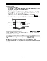
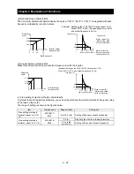
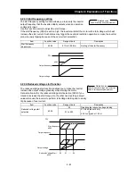
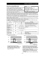
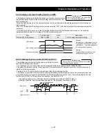
4.2.40 Input terminal a/b (NO/NC) selection
The input terminal a/b (NO/NC) selection function allows you to
specify a-contact or b-contact input for each of the intelligent
input terminals [1] to [8] and the FW terminal.
An a-contact turns on the input signal when closed and turns it off when opened.
An b-contact turns on the input signal when opened and turns it off when closed.
The terminal to which the reset (RS) function is assigned functions only as an a-contact.
Item Function
code
Data
Description
Terminal active state
C011 to C018
00
a-contact (NO)
01
b-contact (NC)
Terminal [FW] active state
C019
00
a-contact (NO)
01
b-contact (NC)
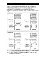
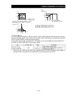
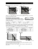
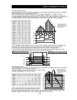
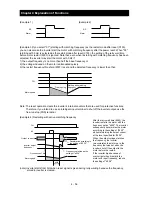
4.2.41 Multispeed select setting (CF1 to CF4 and SF1 to SF7)
The multispeed select setting function allows you to set multiple
motor speeds and switch among them by way of signal input
via specified terminals.
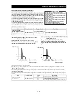
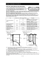
Multispeed operation can be performed in two modes: binary
operation mode (with up to 16 speeds) using four input
terminals and bit operation mode (with up to eight speeds)
using seven input terminals.
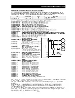
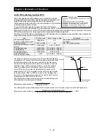
Item Function
code
Data
Description
Multispeed
operation selection
A019
00
Binary operation mode with up to 16 speeds
01
Bit operation mode with up to 8 speeds
Multispeed 0 to 15
settings
A020/A220/
A320
A021 to A035
0.00 or "start frequency" to
"maximum frequency" (Hz)
Setting of the frequency as each speed
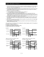
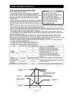
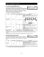
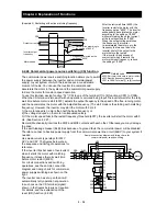
Carefully note that during multispeed operation, the rotation direction specified in an operation command is
reversed if the sum of the frequencies specified by the main frequency and auxiliary frequency commands
is less than 0 Hz when the following settings have been made:
- The control circuit terminal block (01) is specified for the frequency source setting (A001).
- The external analog input (O/O2/OI) mode, set by a combination of [AT] selection (A005), [O2] selection
(A006), and AT terminal On/Off state allows reversible motor operation.
C011 to C018: Terminal [1] to [8] active state
C019: Terminal [FW] active state
Related code
A019: Multispeed operation selection
A020/A220/A320: Multispeed frequency
setting, 1st/2nd/3rd motors
A021 to A035: Multispeed 1 to 15 settings
C001 to C008: Terminal [1] to [8] functions
C169: Multistage speed/position determination
time
Related code
Summary of Contents for L700 Series
Page 16: ... Memo ...
Page 20: ... Memo ...
Page 22: ... Memo ...
Page 46: ... Memo ...
Page 60: ... Memo ...
Page 62: ... Memo ...
Page 212: ... Memo ...
Page 222: ... Memo ...
Page 224: ... Memo ...
Page 232: ... Memo ...
Page 238: ...Chapter 7 Specifications 7 6 L700 750 LFF 6 Cable hole φ41 ...
Page 239: ...Chapter 7 Specifications 7 7 L700 900 to 1100HFF L700 1320 to 1600HFF ...
Page 240: ... Memo ...
Page 242: ... Memo ...
Page 258: ... Memo ...