


Chapter 4 Explanation of Functions
4 - 83
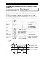
4.2.89 Optimum accel/decel operation function
The optimum accel/decel operation function eliminates the need
for acceleration time and deceleration time settings for the motor
operation by the inverter. Conventional inverters required you to
adjust the acceleration and deceleration time according to the
status of the load. Based on fuzzy logic, this function
automatically adjusts the acceleration and deceleration time to
minimize the inverter performance. This function adjusts the acceleration time so that during acceleration,
the inverter output current does not exceed the current level specified by the deceleration rate at overload
restriction (when the overload restriction is enabled) or about 150% of the inverter's rated current (when
the overload restriction is disabled). This function adjusts the deceleration time so that, during deceleration,
the output current does not exceed about 150% of the inverter's rated current or the DC voltage in the
inverter circuits does not exceed about 370 V (in the case of 200 V class models) or about 740 V (in the
case of 400 V class models). Thus, this function automatically adjusts the acceleration and deceleration
time appropriately on a real-time basis even when the motor load or the motor's moment of inertia
changes.
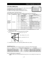
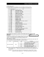
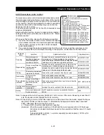
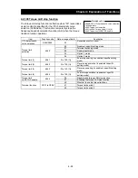
Item Function
code
Data
Description
Operation mode selection
A085
00 Normal
operation
01 Energy-saving
operation
02 Fuzzy
operation
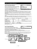
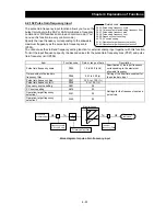
Observe the following precautions and instructions when using this function:
Note 1: This function is not suited for machines that require fixed acceleration and deceleration times. This
function varies the acceleration and deceleration time according to the changes in the load and the
moment of inertia.
Note 2: If the inertial force produced in the machine becomes about 20 times as high as the motor shaft
capacity, the inverter may trip. If this occurs, reduce the carrier frequency.
Note 3: Even when the inverter is driving the same motor, the actual acceleration/deceleration time always
changes according to current fluctuation.
Note 4: The selection of the fuzzy acceleration/deceleration function is valid only when the control mode is
a V/f characteristic control mode. When a sensorless vector control mode is selected, the
selection of this function is ignored (normal operation is performed).
Note 5: When the fuzzy acceleration/deceleration function is enabled, the jogging operation differs from
the normal jogging operation because of fuzzy acceleration.
Note 6: When the fuzzy acceleration/deceleration function is enabled, the deceleration time may be
prolonged if the motor load exceeds the inverter's rated load.
Note 7: If the inverter repeats acceleration and deceleration often, the inverter may trip.
Note 8: Do not use the fuzzy acceleration/deceleration function when the internal regenerative braking
circuit of the inverter or an external braking unit is used. In such cases, the braking resistor
disables the inverter from stopping deceleration at the end of the deceleration time set by the
fuzzy acceleration/deceleration function.
Note 9: When using the inverter for a motor of which the capacity is one class lower than that of the
inverter, enable the overload restriction function and set the overload restriction level to 1.5 times
as high as the rated current of the motor.
Note10: It is likely not to decelerate when the voltage of the power supply is high when Optimum
accel/decel operation function is used. In this case, please cut power off, and stop the motor. And,
please turn on the power supply again, change the setting of this function to Normal operation or
Energy-saving operation, and use it.
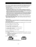
A044/A244/A344: V/F characteristic curve
selection, 1st/2nd/3rd motors
A085: Operation mode selection
b021/b024: Overload restriction operation
mode (1) (2)
b022/b025: Overload restriction setting (1) (2)
Related code
Summary of Contents for L700 Series
Page 16: ... Memo ...
Page 20: ... Memo ...
Page 22: ... Memo ...
Page 46: ... Memo ...
Page 60: ... Memo ...
Page 62: ... Memo ...
Page 212: ... Memo ...
Page 222: ... Memo ...
Page 224: ... Memo ...
Page 232: ... Memo ...
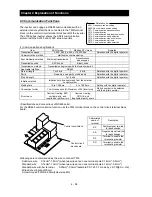
Page 238: ...Chapter 7 Specifications 7 6 L700 750 LFF 6 Cable hole φ41 ...
Page 239: ...Chapter 7 Specifications 7 7 L700 900 to 1100HFF L700 1320 to 1600HFF ...
Page 240: ... Memo ...
Page 242: ... Memo ...
Page 258: ... Memo ...