


Chapter 1 Overview
1 - 3
1.3 Exterior Views and Names of Parts
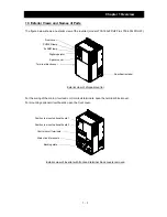
The figure below shows an exterior view of the inverter (model L700-185LFF/HFF to L700-300LFF/HFF).
Exterior view of shipped inverter
For the wiring of the main circuit and control circuit terminals, open the terminal block cover.
For mounting optional circuit boards, open the front cover.
Exterior view of inverter with front and terminal block covers removed
Front cover
POWER lamp
ALARM lamp
Terminal block cover
Spacer cover
Digital operator
Specification label
Position to mount optional board 1
Main circuit terminals
Backing plate
Control circuit terminals
Position to mount optional board 2
Summary of Contents for L700 Series
Page 16: ... Memo ...
Page 20: ... Memo ...
Page 22: ... Memo ...
Page 46: ... Memo ...
Page 60: ... Memo ...
Page 62: ... Memo ...
Page 212: ... Memo ...
Page 222: ... Memo ...
Page 224: ... Memo ...
Page 232: ... Memo ...
Page 238: ...Chapter 7 Specifications 7 6 L700 750 LFF 6 Cable hole φ41 ...
Page 239: ...Chapter 7 Specifications 7 7 L700 900 to 1100HFF L700 1320 to 1600HFF ...
Page 240: ... Memo ...
Page 242: ... Memo ...
Page 258: ... Memo ...