


Chapter 2 Installation and Wiring
2 - 13
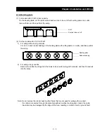
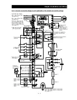
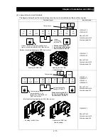
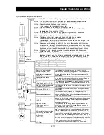
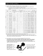
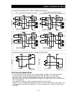
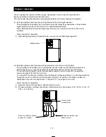
(2) Layout of main circuit terminals
The figures below show the terminal layout on the main circuit terminal block of the inverter.
Terminal layout
Inverter model
RB
R
(L1)
S
(L2)
T
(L3)
PD
(+1)
P
(+)
N
(‑)
U
(T1)
V
(T2)
W
(T3)
R0 T0
チャージランプ
PD‑P
短絡片
DCL
を使用 しない場合、
PD‑P
短絡 片を取り外さ
ないでくださ い。
G
EMC
フィルタ機能
切り替え用短絡片
(
斜線部
)
付き接地端子
G
L700-110LFF
L700-110HFF
R0 and T0: M4
Ground terminal: M5
Other terminals: M5
L700-150LFF
L700-150HFF
R0 and T0: M4
Ground terminal: M5
Other terminals: M6
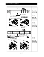
RB
R
(L1)
S
(L2)
T
(L3)
PD
(+1)
P
(+)
N
(‑)
U
(T1)
V
(T2)
W
(T3)
R0 T0
G
G
L700-185 to
L700-220LFF
L700-185 to
L700-300HFF
R0 and T0: M4
Ground terminal: M6
Other terminals: M6
L700-300LFF
R0 and T0: M4
Ground terminal: M6
Other terminals: M8
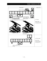
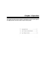
[Method of enabling/disabling the EMC filter function]
Charge lamp
Jumper connecting
terminals PD and P
Ground terminal with
jumper (shaded in the
figure) to enable/disable the
EMC filter function
When not using the DCL,
do not remove the jumper
from terminals PD and P.
Enabling the EMC filter
Disabling the EMC filter
(factory setting)
Disabling the EMC filter
(factory setting)
Enabling the EMC filter
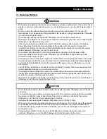
Jumper
connecting
terminals PD
Ground terminal with jumper (shaded in the
figure) to enable/disable the EMC filter function
[Method of enabling/disabling the EMC filter function]
When not using the DCL,
do not remove the jumper
from terminals PD and P.
Charge lamp
Summary of Contents for L700 Series
Page 16: ... Memo ...
Page 20: ... Memo ...
Page 22: ... Memo ...
Page 46: ... Memo ...
Page 60: ... Memo ...
Page 62: ... Memo ...
Page 212: ... Memo ...
Page 222: ... Memo ...
Page 224: ... Memo ...
Page 232: ... Memo ...
Page 238: ...Chapter 7 Specifications 7 6 L700 750 LFF 6 Cable hole φ41 ...
Page 239: ...Chapter 7 Specifications 7 7 L700 900 to 1100HFF L700 1320 to 1600HFF ...
Page 240: ... Memo ...
Page 242: ... Memo ...
Page 258: ... Memo ...