


Chapter 4 Explanation of Functions
4 - 16
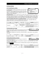
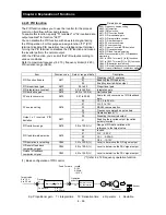
4.2.17 V/F characteristic curve selection
The V/F characteristic curve selection function allows you to set
the output voltage/output frequency (V/f) characteristic.
To switch the V/F characteristic curve selection among the 1st,
2nd, and 3rd settings, assign function "08" (SET) and "17"
(SET3) to intelligent input terminals. Use the SET and SET3
signals for switching.
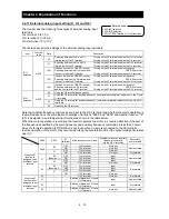
Function code
Data
V/f characteristic
Remarks
A044/A244/
A344
00
Constant torque characteristic (VC)
01
Reduced-torque characteristic
(1.7th power of VP)
02
Free V/f characteristic
Available only for A044 and A244
03
Sensorless vector control (SLV)
Available only for A044 and A244 (See Section
4.2.96.)
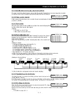
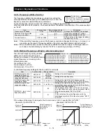
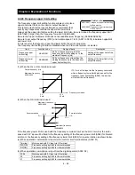
(1) Constant torque characteristic (VC)
With this control system set, the output voltage is in proportion to the output frequency within the range
from 0 Hz to the base frequency. Within the output frequency range over the base frequency up to the
maximum frequency, the output voltage is constant, regardless of the change in the output frequency.
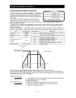
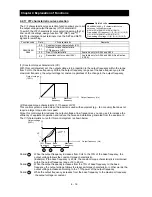
(2) Reduced-torque characteristic (1.7th power of VP)
This control system is suited when the inverter is used with equipment (e.g., fan or pump) that does not
require a large torque at a low speed.
Since this control system reduces the output voltage at low frequencies, you can use it to increase the
efficiency of equipment operation and reduce the noise and vibrations generated from the equipment.
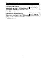
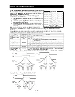
The V/f characteristic curve for this control system is shown below.
Period : While the output frequency increases from 0 Hz to the 10% of the base frequency, the
output voltage follows the constant torque characteristic.
(Example) If the base frequency is 60 Hz, the constant torque characteristic is maintained
within the output frequency range of 0 to 60 Hz.
Period : While the output frequency increases from the 10% of base frequency to the base
frequency, the output voltage follows the reduced-torque characteristic. In other words, the
output voltage increases according to the 1.7th power of the output frequency.
Period :
While the output frequency increases from the base frequency to the maximum frequency,
the output voltage is constant.
A044/A244/A344: V/F characteristic curve
selection, 1st/2nd/3rd motors
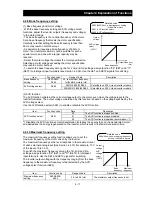
b100/b102/b104/b106/b108/b110/b112:
Free-setting V/f frequency (1) (2) (3) (4) (5) (6) (7)
b101/b103/b105/b107/b109/b111/b113:
Free-setting V/f voltage (1) (2) (3) (4) (5) (6) (7)
Related code
0
Output voltage
(100%)
Base
frequency
Maximum
frequency
Output frequency (Hz)
0
VP
(f
1.7
)
VC
a
b
c
Output voltage
(100%)
Base
frequency
Maximum
frequency
Output frequency (Hz)
10% of base
frequency
a
b
c
Summary of Contents for L700 Series
Page 16: ... Memo ...
Page 20: ... Memo ...
Page 22: ... Memo ...
Page 46: ... Memo ...
Page 60: ... Memo ...
Page 62: ... Memo ...
Page 212: ... Memo ...
Page 222: ... Memo ...
Page 224: ... Memo ...
Page 232: ... Memo ...
Page 238: ...Chapter 7 Specifications 7 6 L700 750 LFF 6 Cable hole φ41 ...
Page 239: ...Chapter 7 Specifications 7 7 L700 900 to 1100HFF L700 1320 to 1600HFF ...
Page 240: ... Memo ...
Page 242: ... Memo ...
Page 258: ... Memo ...