


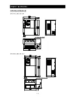


Chapter 7 Specifications
7 - 1
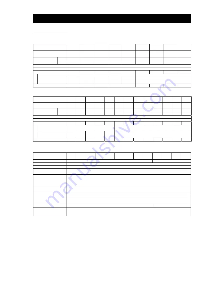
7.1 Specifications
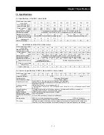
(1) Specifications of the 200 V class model
Model name (type name)
L700-XXXLFF
110 150 185 220 300 370 450 550 750
Max. applicable motor
capacity (4-pole) (kW)
11 15 18.5 22 30 37 45 55 75
Rated capacity
(kVA)
200V
15.2 20.0 26.3 29.4 39.1 49.5 59.2 72.7 93.5
240V
18.2 24.1 31.5 35.3 46.9 59.4 71 87.2 112.2
Rated input AC voltage
Three-phase (3-wire), 200 to 240 V (+10%, -15%), 50/60 Hz (±5%)
Rated output voltage
Three-phase (3-wire), 200 to 240 V (corresponding to the input voltage)
Rated output current (A)
44 58 73 85 113 140
169 210 270
Braking
Regenerative braking
Internal BRD circuit (external discharge resistor)
External regenerative braking unit
Minimum connectable
resistance (
Ω
)
10 10 7.5 7.5 5
-
Approx. weight (kg)
6 6 14 47 14 22 30 30 43
(2)
Specifications of the 400 V class model
Model name (type name)
L700-XXXHFF
110 150 185 220 300 370 450 550 750 900 1100 1320
1600
Max. applicable motor
capacity (4-pole) (kW)
11 15 18.5
22 30 37 45 55 75 90 110 132 160
Rated capacity
(kVA)
400V 15.2 20.9 25.6
30.4
39.4
48.4
58.8
72.7
93.5
110.8 135 159.3 200.9
480V 18.2 24.1 30.7
36.5
47.3
58.1
70.6
87.2
112.2 133 162.1 191.2 241.1
Rated input AC voltage
Three-phase (3-wire), 380 to 480 V (+10%, -15%), 50/60 Hz (±5%)
Rated output voltage
Three-phase (3-wire), 380 to 480 V (corresponding to the input voltage)
Rated output current (A)
22 29 37 43 57 70 85 105
135
160 195
230
290
Braking
Regenerative braking
Internal BRD circuit
(external discharge resistor)
External regenerative braking unit
Minimum connectable
resistance (
Ω
)
35 35 24 24 20
-
Approx.
weight
(kg) 6 6 14 14 14 22 30 30 30 55 55 70 70
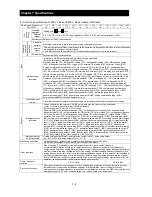
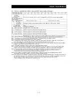
(3) Common specifications of 200 V class and 400 V class models
Model name (type name)
L700-XXXFF
110
L/H
150
L/H
185
L/H
220
L/H
300
L/H
370
L/H
450
L/H
550
L/H
750
L/H
900
H
1100
H
1320
H
1600
H
Protective structure
IP20
IP00
Control system
Sine-wave PWM control
Output frequency range
0.1 to 400 Hz (Note3)
Frequency accuracy
Within ±0.01% of the maximum output frequency for digital input,
within ±0.2% of maximum frequency for digital input (at 25±10
°
C)
Frequency setting
resolution
Digital input: 0.01 Hz
Analog input: Maximum output frequency/4000
(O terminal input: 12 bits/0 to +10 V, O2 terminal input: 12 bits/-10 to +10 V, OI terminal input: 12 bits/0
to +20 mA)
Voltage/frequency
characteristic
V/f characteristic variable with the base frequency set between 30 to 400 Hz, constant- or
reduced-torque V/f control, sensorless vector control
Speed fluctuation
±
0.5% (with sensorless vector control) Note8)
Rated overload current
120% / 60 seconds
Acceleration/deceleration
time
0.01 to 3,600.0 seconds (in linear or curved pattern)
Starting torque
150% / 0.5 Hz (with sensorless vector control)
120% / 0.5Hz (do to
)
DC braking
Triggered at motor start-up, when the actual motor frequency exceeds the acceleration frequency set
by a stop command, when the actual motor frequency exceeds the frequency set by a frequency
command, or by an externally input command (braking force, time, and frequency are variable).
Summary of Contents for L700 Series
Page 16: ... Memo ...
Page 20: ... Memo ...
Page 22: ... Memo ...
Page 46: ... Memo ...
Page 60: ... Memo ...
Page 62: ... Memo ...
Page 212: ... Memo ...
Page 222: ... Memo ...
Page 224: ... Memo ...
Page 232: ... Memo ...
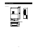
Page 238: ...Chapter 7 Specifications 7 6 L700 750 LFF 6 Cable hole φ41 ...
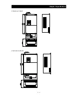
Page 239: ...Chapter 7 Specifications 7 7 L700 900 to 1100HFF L700 1320 to 1600HFF ...
Page 240: ... Memo ...
Page 242: ... Memo ...
Page 258: ... Memo ...