


Chapter 2 Installation and Wiring
2 - 18
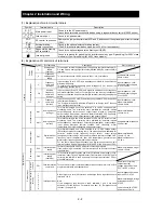
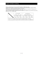
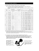
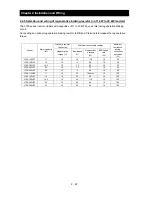
(4) Recommended cable gauges, wiring accessories, and crimp terminals
Note: For compliance with CE and UL standards, see the safety precautions concerning EMC and the
compliance with UL and cUL standards under Safety Instructions.
The table below lists the specifications of cables, crimp terminals, and terminal screw tightening torques for
reference.
Motor
output
(kW)
Applicable inverter
model
Gauge of power
line cable (mm
2
)
(Terminals: R, S,
T, U, V, W, P, PD,
and N)
Grounding
cable (mm
2
)
External braking
resistor across
terminals P and
RB (mm
2
)
Size of
terminal
screw
Crimp
terminal
Tightening
torque (N-m)
Applicable device
Earth-leakage
breaker (ELB)
Magnetic
contactor
(MC)
200 V
cl
ass
11 L700-110LFF
14
14
14
M5 R14-5
2.4(MAX4.0)
RX100
(75A)
HK50
15 L700-150LFF
22
22
14
M6 22-6
4.0(MAX4.4)
RX100 (100A)
H65
18.5 L700-185LFF
30
22
22
M6 38-6
4.5(MAX4.9)
RX100 (100A)
H80
22 L700-220LFF
38
30
22
M6 38-6
4.5(MAX4.9) RX225B (150A)
H100
30 L700-300LFF 60
(22
×
2) 30
30 M8
R60-8
8.1(MAX8.8) RX225B (200A)
H125
37 L700-370LFF 100
(38
×
2) 38
―
M8
100-8
8.1(MAX8.8) RX225B (225A)
H150
45 L700-450LFF 100
(38
×
2) 38
―
M8
100-8
8.1(MAX20) RX225B (225A)
H200
55 L700-550LFF 150
(60
×
2) 60
―
M8
150-8
8.1(MAX20) RX400B (350A)
H250
75 L700-750LFF 150 (60
×
2) 80
―
M10
R150-10 19.5(MAX22) RX400B (350A)
H300
400 V
cl
ass
11 L700-110HFF
5.5
5.5
5.5
M5
R5.5-5
2.4(MAX4.0)
EX50C (30A)
HK35
15 L700-150HFF
8
8
5.5
M6 R8-6
4.0(MAX4.4)
EX60B (60A)
HK35
18.5 L700-185HFF
14
14
8
M6 R14-6
4.5(MAX4.9)
EX60B (60A)
HK50
22 L700-220HFF
14
14
8
M6 R14-6
4.5(MAX4.9)
RX100 (75A)
HK50
30 L700-300HFF
22
22
14
M6 R22-6
4.5(MAX4.9)
RX100 (100A)
H65
37 L700-370HFF
38
22
―
M6
38-6
4.5(MAX4.9)
RX100 (100A)
H80
45 L700-450HFF
38
22
―
M8
R38-8
8.1(MAX20) RX225B (150A)
H100
55 L700-550HFF
60
30
―
M8
R60-8
8.1(MAX20)
RX255B
(175A)
H125
75 L700-750HFF 100(38X2)
38
―
M8
100-8
8.1(MAX20)
RX225B(225A)
H150
90 L700-900HFF 100(38X2)
38
―
M10
R100-10 20.0(MAX22)
RX225B(225A)
H200
110 L700-1100HFF 150(60X2)
60
―
M10
R150-10 20.0(MAX35)
RX400B(350A)
H250
132 L700-1320HFF
80X2 80
―
M10
80-10
20.0(MAX35) RX400B(350A) H300
160 L700-1600HFF 100X2
80
―
M10
R100-10 20.0(MAX35)
RX400B(350A)
H400
Note: Cable gauges indicate those of HIV cables (maximum heat resistance: 75°C).
*1
)
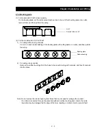
Please use the round type crimp terminals ( for the UL standard) suitable for the use electric wire when you
connect the electric wire with the main circuit terminal stand. Please put on pressure to the crimp terminals l with a
crimp tool that the terminal stand maker recommends.
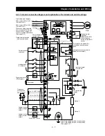
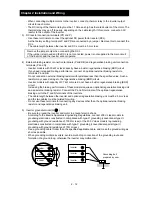
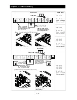
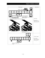
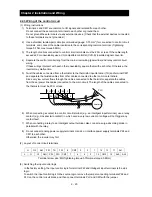
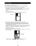
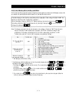
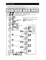
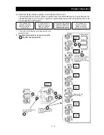
(5) Connecting the control circuit to a power supply separately from the main circuit
If the protective circuit of the inverter operates to open the magnetic contactor in the input power
supply circuit, the inverter control circuit power is lost, and the alarm signal cannot be retained.
To retain the alarm signal, connect control circuit terminals R0 and T0 to a power supply.
In details, connect the control circuit power supply terminals R0 and T0 to the primary side of the
magnetic contactor as shown below.
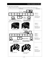
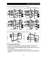
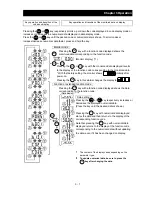
(Connection method)
Power-receiving specifications
200 V class model:
200 to 240 V (+10%, -15%)
(50/60 Hz ±5%),(282 to 339 VDC)
400 V class model:
380 to 480 V (+10%, -15%)
(50/60 Hz ±5%),(537 to 678 VDC)
②
Remove the J51 connector.
①
Remove the connected cables.
③
Connect the control circuit power
supply cables to the control
circuit power supply terminal
block.
J51
Summary of Contents for L700 Series
Page 16: ... Memo ...
Page 20: ... Memo ...
Page 22: ... Memo ...
Page 46: ... Memo ...
Page 60: ... Memo ...
Page 62: ... Memo ...
Page 212: ... Memo ...
Page 222: ... Memo ...
Page 224: ... Memo ...
Page 232: ... Memo ...
Page 238: ...Chapter 7 Specifications 7 6 L700 750 LFF 6 Cable hole φ41 ...
Page 239: ...Chapter 7 Specifications 7 7 L700 900 to 1100HFF L700 1320 to 1600HFF ...
Page 240: ... Memo ...
Page 242: ... Memo ...
Page 258: ... Memo ...