54
Chapter
4
•
•
•
•
•
•
Step 3.
Click Save Parameters.
Configuring EtherNet/IP from the Front Panel
Step 1.
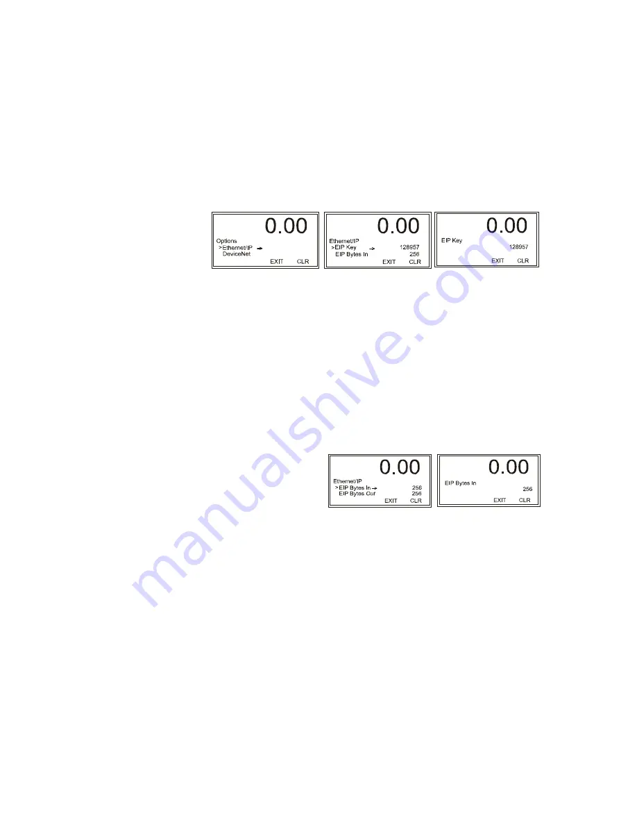
From the Configuration Menu, use the down arrow to select EtherNet/IP and
press Enter to display the EtherNet/IP menu. Use the down arrow to select EIP
Key, then press Enter to display the EIP edit page.
Step 2.
Use the left or right arrow to position the cursor and the up or down arrow to select
the values. Enter key number you received from the HI Service Center and press
Enter to save it. Note that the number displayed above is only for illustration
purposes and is based on the serial number.
Step 3.
You will have to set the following parameters on your PLC in order to
communicate with the HI 4050:
•
COMM FORMAT: SINT, INT, DINT, OR FLOAT. Recommended as
DATA-INT
•
INPUT INSTANCE 100, LENGTH 0-256
•
OUTPUT INSTANCE 112 - LENGTH 0-256
•
CONFIGURATION INSTANCE 150 - LENGTH 0
Step 4.
From the Ethernet IP menu, select EIP Bytes Input to open the edit form.
Step 5.
Use the left or right
arrow to position the
cursor and the up or
down arrow to select
the values.
Step 6.
Use the left arrow to move to the next digit and enter the number of bytes you
require for your application. Our example shows 256 bytes.
Step 7.
Use the same procedure used to enter the EIP Bytes In value to enter the EIP Bytes
Out value.
Step 8.
The read-only Connected entry confirms that the 4050 is connected to the
network. If the instrument is not connected to the network, a message appears
saying “Not Connected.” Check the EtherNet/IP connection at the rear of the
instrument to make sure it is securely fastened to the EtherNet/IP port.
Summary of Contents for HI 4050
Page 18: ...8 Chapter 1 ...
Page 24: ...14 Chapter 2 ...
Page 116: ...108 Chapter 5 ...
Page 184: ...4 Appendix A ...
Page 191: ......


