CHAPTER 2: INSTALL ATION/CONFIGURATION
2.58
EP OS MOTOR MANAGEMENT SYSTEM – INSTRUCTION MANUAL
Refer to Tables 2-6 and 2-7 for the complete input, output, timer and control configurations of the Dahlander
motor starter.
Figures 2-24 and 2-25 show typical Dahlander starter diagrams for EntelliPro ES3 and EntelliPro ES5.
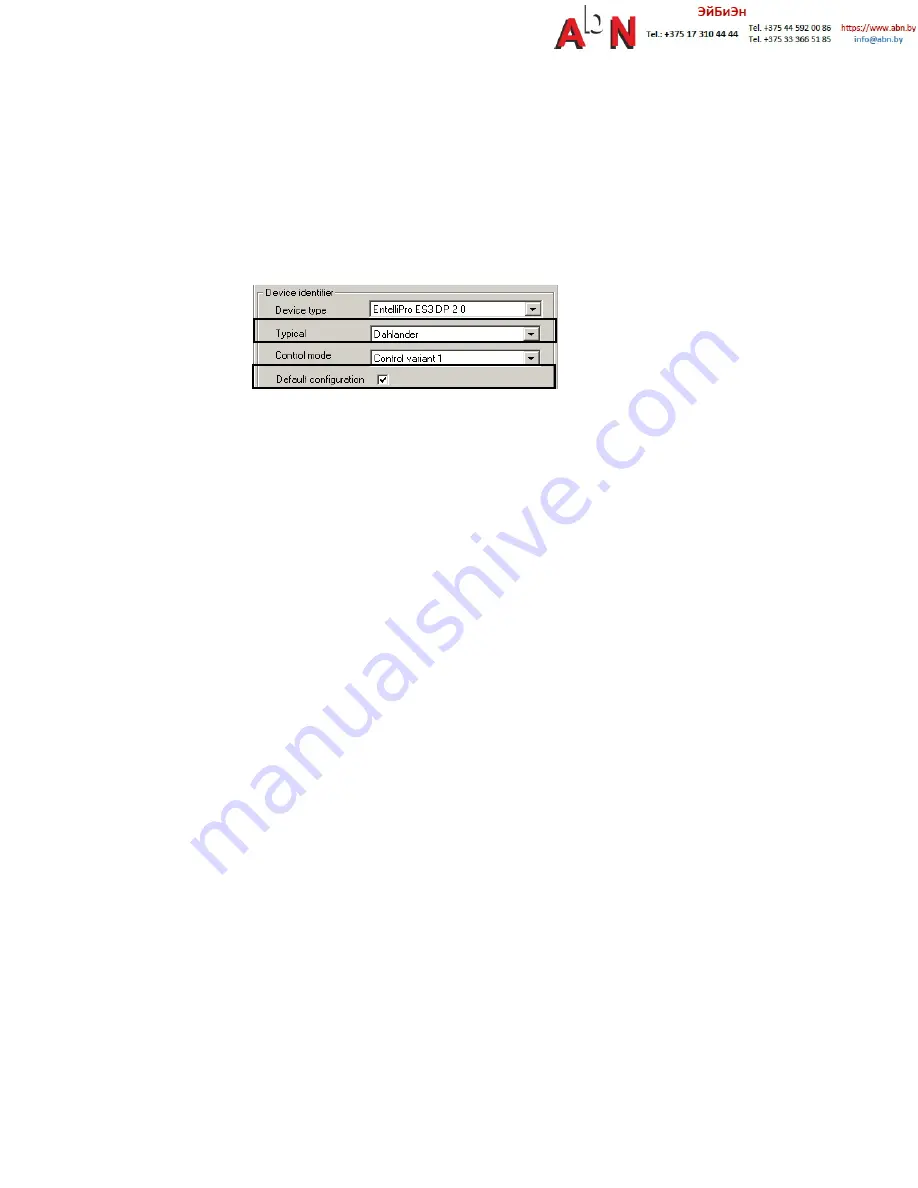
If the default configuration and the Dahlander typical are selected in the WinESG parameterization/information
panel shown in the illustration below or by setting Modbus function code 6 register 62 bit0 to 1 and bits 8,9,10
and 11 to 0x6,the inputs and outputs are mapped as below:
For EntelliPro ES3 types:
Input 99 is mapped to contactor 1 feedback
- active high
Input 98 is mapped to contactor 2 feedback
- active high
Input 97 is mapped to contactor Y feedback
- active low
Input 96 is mapped to main circuit feedback
- active low
Input 95 is mapped to emergency stop
- active low
Input 94 is mapped to external supervision
- active high
Input 93 is mapped to safety circuit
- active low
Output 41 is mapped to contactor 1
Output 43 is mapped to contactor 2
Output 45 is mapped to contactor Y
For EntelliPro ES5 types:
Input 99 is mapped to contactor 1 feedback
- active high
Input 98 is mapped to contactor 2 feedback
- active high
Input 97 is mapped to contactor Y feedback
- active high
Input 96 is mapped to drawer in test mode
- active high
Input 95 is mapped to drawer in operation mode
- active high
Input 94 is mapped to main circuit feedback
- active low
Input 93 is mapped to control circuit
- active low
Input 11 is mapped to command OFF
- active low
Input 12 is mapped to command slow ON1
- active high
Input 13 is mapped to command fast ON2
- active high
Input 14 is mapped to external supervision
- active high
Input 15 is mapped to reset alarm
- active high
Input 16 is mapped to emergency stop
- active low
Input 17 is mapped to safety circuit
- active low


