3.20
EP OS MOTOR MANAGEMENT SYSTEM – INSTRUCTION MANUAL
CHAPTER
3
:
MOTOR PROTECTION
3.3 Ground fault
The ground fault function is designed for grounded networks. The ground fault current is derived by summing the CT’s
secondary currents.
Ground fault is disabled when the average current falls below half of the motor load setting or exceeds 3 times
the motor load setting.
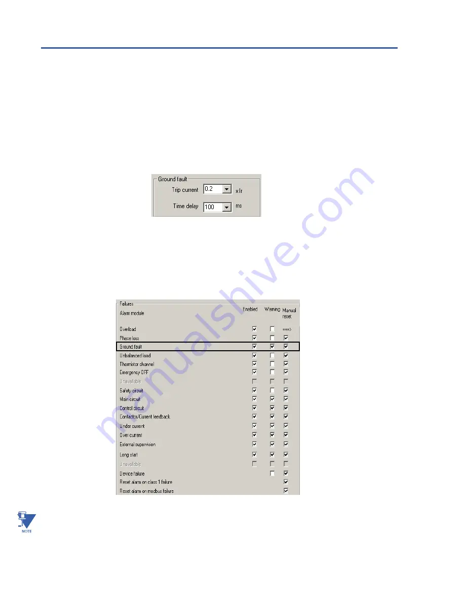
Ground fault trip current and delay band are set in WinESG parameterization/device settings panel shown in the
illustration below or Modbus function code 06 register 56.
Trip current is set from 0.2 to 1.0 x Ir in 0.1 increments. The time delay is set from 100 to 1000 msec in 100 msec
increments.
Ground fault can be enabled or disabled, set as a warning or failure and requiring an auto or manual reset after
a failure, in WinESG parameterization/alarms panel shown in illustration below or Modbus function code 6
registers 114 (enable/disable), 64 (warning/failure), and 63 (auto/manual reset).
NOTE:
The polarity of the phase CTs is critical for the negative-sequence unbalance calculation, power
measurement , and residual ground current detection (if used). GF is only available on 3-phase system.


