2. HORIZONTAL MODE
2-11
2.4.5 Suitable
tilt
angle
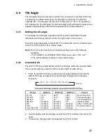
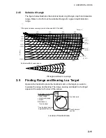
The figure below illustrates the relationship among tilt angle, depth and detection
range. Refer to it to find out the suitable tilt angle for a given depth/detection
range.
Range(m)
Vertical width of sonar beam
18
°
31 m
100 m
100 m
300 m
93 m
200 m
Depth (m)
62 m
Tilt angle and beam coverage (vertical beamwidth 18
°
at -6dB
)
100
(200)
200
(400)
300
(600)
400
(800)
Tilt 0
˚
(0˚
‑
9˚)
20(40)
40(80)
60(120)
80(160)
100(200)
200(400)
Tilt 5
˚
(0˚
‑
14˚)
Tilt 15
˚
(6˚
‑
24˚)
Grey: Tilt 10
˚
(1˚
‑
19˚)
(-6dB)
Tilt angle and beam coverage
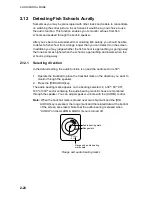
2.5
Finding Range and Bearing to a Target
Operate the trackball to place the trackball mark on the target you want to
measure the range and bearing. The range, bearing and depth to the target
appear at the upper left corner of the screen.
B
Trackball mark
TRACKBALL DATA
Slant range
Horizontal range
Depth
B Relative or
True bearing*
*True bearing requires
appropriate sensor.
34
°
56.789N
123
°
45.678E
Trackball mark
position
Location of trackball data
Summary of Contents for FSV-30
Page 1: ...COLOR SCANNING SONAR FSV 30 ...
Page 14: ...This page is intentionally left blank ...
Page 30: ...1 OPERATIONAL OVERVIEW 1 16 This page is intentionally left blank ...
Page 80: ...2 HORIZONTAL MODE 2 50 The page is intentionally left blank ...
Page 100: ...3 VERTICAL MODE 3 20 The page is intentionally left blank ...
Page 122: ...5 6 This page is intentionally left blank ...
Page 136: ...7 10 This page is intentionally left blank ...
Page 152: ...8 OTHERS MENU 8 16 This page is intentionally left blank ...
Page 170: ...10 MAINTENANCE TROUBLESHOOTING 10 14 This page is intentionally left blank ...
Page 174: ...SP 4 This page is intentionally left blank ...
Page 182: ...ORIGINAL SETTING AP 8 New Original setting ...
Page 183: ...ORIGINAL SETTING AP 9 ...
Page 184: ...ORIGINAL SETTING AP 10 ...
Page 185: ...ORIGINAL SETTING AP 11 Color setting ...
Page 186: ...ORIGINAL SETTING AP 12 Color Response Curve setting ...

