x
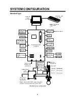
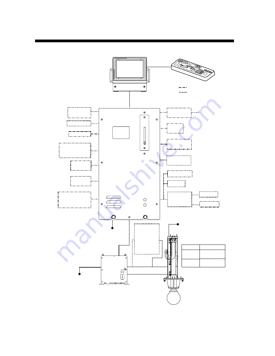
SYSTEM CONFIGURATION
Standard type
Note 1: Power Kit FSV-2403 (option, installed in
processor unit) required to connect CS-120A.
TRANSCEIVER
UNIT
FSV-301
100/110/115/
220/230 VAC,
1
φ,
50-60 Hz
PROCESSOR UNIT
FSV-3002
Loudspeaker
Sub Monitor
Echo Sounder,
Current Indicator,
other
Navigator 1
Navigator 2
AD Converter
AD-100
Current
Indicator
Current
Indicator/Log
E/S Interface
VI-1100A
Net Recorder
VI-1100A
Net Sonde
Junction Box
CS-170
VI-1100A
Net Sonde
External
Interface CS-120A
(Note 1)
100/110/115/
220/230 VAC,
1
φ,
50-60 Hz
CONTROL UNIT
FSV-3001
MONITOR
UNIT
FSV-2400
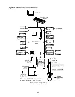
Local Supply
Option
Gyrocompass
FUSE
MAIN SW
CHARGE
OV ERR
BV ERR
220 VAC,
3
φ,
50-60 Hz
Hull unit
Specifications
FSV-303
1200 mm stroke
FSV-304
1600 mm stroke
HULL UNIT
Cable for
Extension Kit
FSV-305-5 or
FSV-305-15
(incl. Junction
Box)
Control unit
FSV-3001
Standard type configuration
Summary of Contents for FSV-30
Page 1: ...COLOR SCANNING SONAR FSV 30 ...
Page 14: ...This page is intentionally left blank ...
Page 30: ...1 OPERATIONAL OVERVIEW 1 16 This page is intentionally left blank ...
Page 80: ...2 HORIZONTAL MODE 2 50 The page is intentionally left blank ...
Page 100: ...3 VERTICAL MODE 3 20 The page is intentionally left blank ...
Page 122: ...5 6 This page is intentionally left blank ...
Page 136: ...7 10 This page is intentionally left blank ...
Page 152: ...8 OTHERS MENU 8 16 This page is intentionally left blank ...
Page 170: ...10 MAINTENANCE TROUBLESHOOTING 10 14 This page is intentionally left blank ...
Page 174: ...SP 4 This page is intentionally left blank ...
Page 182: ...ORIGINAL SETTING AP 8 New Original setting ...
Page 183: ...ORIGINAL SETTING AP 9 ...
Page 184: ...ORIGINAL SETTING AP 10 ...
Page 185: ...ORIGINAL SETTING AP 11 Color setting ...
Page 186: ...ORIGINAL SETTING AP 12 Color Response Curve setting ...


