1. OPERATIONAL OVERVIEW
1-9
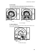
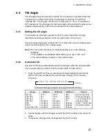
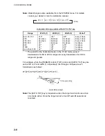
V1 and V2 modes
The V1 and V2 modes show a vertical slice of the bearing selected by the
vertical bearing mark on the horizontal display. The vertical 2 mode provides two
vertical slices. Chapter 3 discusses the vertical mode.
N
W
S
E
2000
NUMERIC/
GRAPHIC
DATA
DISPLAY
1000
1500
500
1000
1500
500
1000
500
N
W
S
E
2000
NUMERIC/
GRAPHIC
DATA
DISPLAY
1000
1500
500
1000
500
Vertical 1 Display
Vertical 1 Display
Vertical 2 Display
V1 mode
V1 & V2 mode
V 52
°
V1 and V2 displays
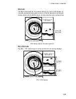
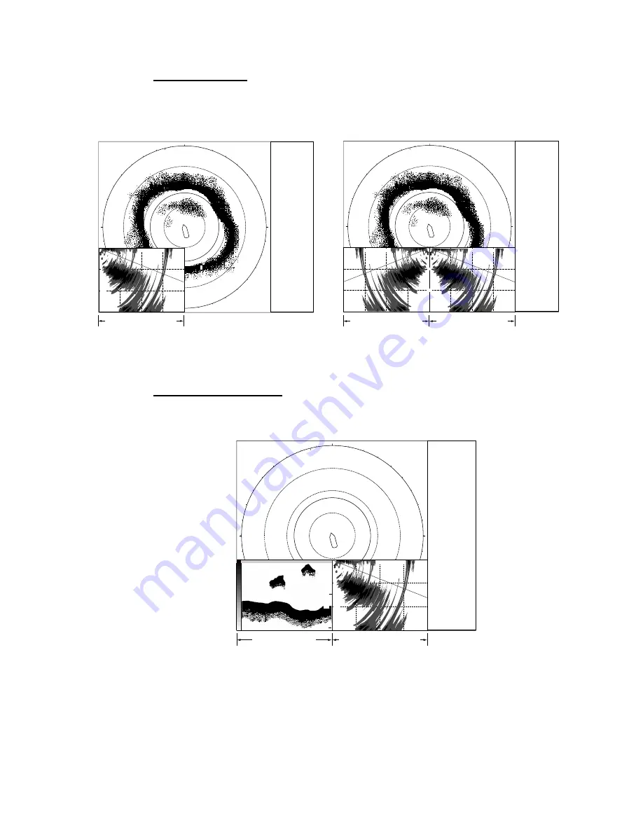
V1 + ES1 (or ES2) mode
The V1 + ES1 (or ES2) combines the vertical 1 display with the picture from an
echo sounder or a net recorder.
N
W
S
E
2000
NUMERIC/
GRAPHIC
DATA
DISPLAY
1000
500
1000
500
Echo sounder
Display
(ES 1 or ES 2)
Vertical 1 Display
30
60
0
1500
V1 & ES1 (ES2) display
Summary of Contents for FSV-30
Page 1: ...COLOR SCANNING SONAR FSV 30 ...
Page 14: ...This page is intentionally left blank ...
Page 30: ...1 OPERATIONAL OVERVIEW 1 16 This page is intentionally left blank ...
Page 80: ...2 HORIZONTAL MODE 2 50 The page is intentionally left blank ...
Page 100: ...3 VERTICAL MODE 3 20 The page is intentionally left blank ...
Page 122: ...5 6 This page is intentionally left blank ...
Page 136: ...7 10 This page is intentionally left blank ...
Page 152: ...8 OTHERS MENU 8 16 This page is intentionally left blank ...
Page 170: ...10 MAINTENANCE TROUBLESHOOTING 10 14 This page is intentionally left blank ...
Page 174: ...SP 4 This page is intentionally left blank ...
Page 182: ...ORIGINAL SETTING AP 8 New Original setting ...
Page 183: ...ORIGINAL SETTING AP 9 ...
Page 184: ...ORIGINAL SETTING AP 10 ...
Page 185: ...ORIGINAL SETTING AP 11 Color setting ...
Page 186: ...ORIGINAL SETTING AP 12 Color Response Curve setting ...

