


282
Upgrade and Maintenance Manual
BX924
S3
Appendix
11.3
Connectors and indicators
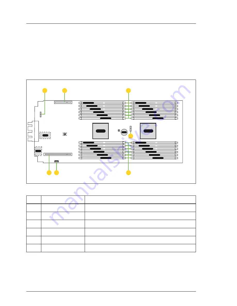
11.3.1 Connectors and indicators on the system board
11.3.1.1 Onboard connectors
Figure 125: Internal connectors of system board D3143
No. Print
Description
A
SSD 0
Connector for SSD 0
B
Mezzanine card 1 Connector for mezzanine card 1
C
Memory modules
Connectors for memory modules
D
SSD 1
Connector for SSD 1
F
Onboard USB
Connector for onboard USB port
G
Mezzanine card 2 Connector for mezzanine card 2
CPU 1
CPU 2
Batt.
TPM
UFM
DIMM 3H
DIMM 2H
DIMM 1H
DIMM 3G
DIMM 1G
DIMM 2G
DIMM 1E
DIMM 2E
DIMM 3E
DIMM 1F
DIMM 3F
DIMM 2F
DIMM 1C
DIMM 3D
DIMM 2D
DIMM 2C
DIMM 3C
DIMM 1D
DIMM 3B
DIMM 2B
DIMM 1B
DIMM 3A
DIMM 1A
DIMM 2A
C
A
C
B
C
C
C
C
C
D
C
F
C
G
Summary of Contents for PRIMERGY BX924 S3
Page 6: ...Upgrade and Maintenance Manual BX924 S3 ...
Page 16: ...16 Upgrade and Maintenance Manual BX924 S3 ...
Page 20: ...20 Upgrade and Maintenance Manual BX924 S3 Introduction ...
Page 42: ...42 Upgrade and Maintenance Manual BX924 S3 Important information ...
Page 68: ...68 Upgrade and Maintenance Manual BX924 S3 Basic hardware procedures ...
Page 104: ...104 Upgrade and Maintenance Manual BX924 S3 Basic software procedures ...
Page 180: ...180 Upgrade and Maintenance Manual BX924 S3 Main memory ...
Page 232: ...232 Upgrade and Maintenance Manual BX924 S3 Processors ...
Page 278: ...278 Upgrade and Maintenance Manual BX924 S3 System board components ...


