EPSON Stylus COLOR 900/900N
Chapter 4 Disassembly and Assembly
89
4.2 Disassembly Procedures
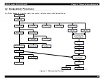
For efficient disassembly, remove printer components in the order shown in the flowchart below.
Figure 4-1. Disassembly Flowchart
START
Upper Case
Printhead
CR Motor
CR HP Sensor
Encoder Belt
Pump Unit
W iring Harness
Printer Mechanism
Main Logic Board
Relay Board and
Cooling Fan
Shield Plates
Pump/ASF Motor and
Solenoid Assembly
Power Supply Board
PF Motor
ASF Unit Removal
ASF Disassembly
ASF Sensor
ASF Feed Rollers
CR Unit
Remove both the CR
Unit and the Pump Unit
before continuing
PE Frame
PE Roller
Platen
Remove both the ASF
Unit and the Platen
before continuing
Top Frame
PE Sensor
PF Roller
Summary of Contents for 900N
Page 1: ...EPSONStylusCOLOR900 900N Color ink jet printer TM SC900 N 6 59 0 18 ...
Page 8: ... 37 5 PRODUCTDESCRIPTION ...
Page 37: ... 37 5 OPERATINGPRINCIPLES ...
Page 67: ... 37 5 TROUBLESHOOTING ...
Page 89: ... 37 5 DISASSEMBLYANDASSEMBLY ...
Page 121: ... 37 5 ADJUSTMENTS ...
Page 156: ... 37 5 MAINTENANCE ...
Page 169: ... 37 5 APPENDIX ...
Page 179: ...EPSON Stylus COLOR 900 900N Chapter 7 Appendix 176 Figure 7 3 C265 Main Board Soldering side ...
Page 181: ...EPSON Stylus COLOR 900 900N Chapter 7 Appendix 178 Figure 7 6 C265 PNL Board ...
Page 195: ...06 03 01 02 for S E ASIA 03 03 05 03 04 EPSON STYLUS COLOR 900 No 7 10056 Rev 01 ...
Page 197: ......
Page 198: ......
Page 199: ......
Page 200: ......
Page 201: ......


