EPSON Stylus COLOR 900/900N
Chapter 6 Maintenance
159
6.7.1 Lubrication Points
Use the table below for guidance when lubricating parts.
NOTE:
Use a syringe to apply all lubricants. For the most control,
use the smallest-diameter syringe available.
When applying grease, extrude a bead 1 mm wide and as
great in length as that indicated under “Amount.”
Never use a syringe without a needle in it.
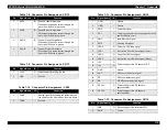
Table 6-3. Lubrication Points
No.
Lubrication Point
Lubricant
Type
Amount
Ref. figure
1
Oil Pad on the bottom of the carriage
See
O-8
0.7 - 0.75 cc
—
2
Carriage Guide Shaft
See
O-8
0.7 - 0.75 cc
—
3
The back of the CR Guide Rail
(located on top of the Top Frame)
G-26
1
×
150 mm
4
The axle shaft in the Pulley
Tensioning Mechanism
G-26
1
×
1 mm
5
Two U-shaped forks on the Rear
Paper Guide where they come in
contact with the PF roller
G-26
1
×
5 mm, top
and bottom of
each fork
6
The left and right PF roller bushings
• After applying the grease, rotate
the paper feed roller to distribute it
evenly on the bushings.
• Apply the grease to the right
bushing from the paper path side
and wipe off any excess grease
that comes out near the capping
mechanism.
G-26
1
×
10 mm
7
The left and right PE roller bushings
• After applying the grease, rotate
the roller to distribute it evenly.
G-26
1
×
2 mm
8
The teeth of the gears on the left side
of the printer:
• PF motor gear
• PF roller gear
• PE roller gear
• intermediate gear
After applying the grease, rotate the
gears to distribute it evenly.
G-26
Apply to
about 1/4 to
1/3 of each
gear’s teeth.
—
9
The axle pin on the intermediate gear
referred to in Step 8
G-26
1
×
10 mm
—
10
In the Pump/ASF switching
mechanism, the larger gear section of
Combination Gear (14.4, 24)
• Lubricate only the gear surface
that comes in contact with the
metal drive gear.
G-26
1 mm
×
1/4 of
the circumfer-
ence of the
gear
11
In the Pump/ASF switching
mechanism, the smaller gear section
of Combination Gear (12,26)
• This is the uppermost combination
gear in the switching mechanism.
G-26
1 mm
×
1/3 of
the circumfer-
ence of the
gear
—
12
In the Pump/ASF switching
mechanism, the teeth of the planetary
gear (the gear that swings up or
down)
G-26
1 mm
×
1/3 of
the circumfer-
ence of the
gear
—
13
In the Pump/ASF switching
mechanism, the gear shafts
G-26
1
×
10 mm
—
14
The teeth of the gears in the Pump
Unit.
G-26
1 mm
×
1/4 of
the circumfer-
ence of the
gear
—
Table 6-3. Lubrication Points (continued)
No.
Lubrication Point
Lubricant
Type
Amount
Ref. figure
Summary of Contents for 900N
Page 1: ...EPSONStylusCOLOR900 900N Color ink jet printer TM SC900 N 6 59 0 18 ...
Page 8: ... 37 5 PRODUCTDESCRIPTION ...
Page 37: ... 37 5 OPERATINGPRINCIPLES ...
Page 67: ... 37 5 TROUBLESHOOTING ...
Page 89: ... 37 5 DISASSEMBLYANDASSEMBLY ...
Page 121: ... 37 5 ADJUSTMENTS ...
Page 156: ... 37 5 MAINTENANCE ...
Page 169: ... 37 5 APPENDIX ...
Page 179: ...EPSON Stylus COLOR 900 900N Chapter 7 Appendix 176 Figure 7 3 C265 Main Board Soldering side ...
Page 181: ...EPSON Stylus COLOR 900 900N Chapter 7 Appendix 178 Figure 7 6 C265 PNL Board ...
Page 195: ...06 03 01 02 for S E ASIA 03 03 05 03 04 EPSON STYLUS COLOR 900 No 7 10056 Rev 01 ...
Page 197: ......
Page 198: ......
Page 199: ......
Page 200: ......
Page 201: ......


