EPSON Stylus COLOR 900/900N
Chapter 6 Maintenance
160
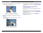
Figure 6-1. Carriage Guide Rail Lubrication
Figure 6-2. Pulley Tensioning Mechanism Lubrication
15
The shafts on which the gears are
mounted in the Pump Unit
• Avoid getting grease between the
CR lock mechanism and the gear
that turns it.
G-26
1
×
1 mm
—
16
The plastic part of the Wiper Blade
where it slides against the frame of
the Pump Unit.
• Avoid getting grease on the rubber
or felt part of the blade itself.
G-26
Apply a small
amount to the
friction
surfaces.
—
17
The ASF drive shaft hole in the right
side of the ASF frame
• Use a brush to apply the grease
evenly to the entire inside surface
of the hole.
G-26
1
×
1 mm
Figure 6-6
18
The right and left Hopper Release
Latches in the ASF unit
• Use a brush to apply the grease
evenly.
G-26
1
×
2 mm
Figure 6-7
Table 6-3. Lubrication Points (continued)
No.
Lubrication Point
Lubricant
Type
Amount
Ref. figure
C R G u i d e R a i l
( b e t w e e n a r r o w s )
P u l l e y T e n s i o n i n g
M e c h a n i s m
Summary of Contents for 900N
Page 1: ...EPSONStylusCOLOR900 900N Color ink jet printer TM SC900 N 6 59 0 18 ...
Page 8: ... 37 5 PRODUCTDESCRIPTION ...
Page 37: ... 37 5 OPERATINGPRINCIPLES ...
Page 67: ... 37 5 TROUBLESHOOTING ...
Page 89: ... 37 5 DISASSEMBLYANDASSEMBLY ...
Page 121: ... 37 5 ADJUSTMENTS ...
Page 156: ... 37 5 MAINTENANCE ...
Page 169: ... 37 5 APPENDIX ...
Page 179: ...EPSON Stylus COLOR 900 900N Chapter 7 Appendix 176 Figure 7 3 C265 Main Board Soldering side ...
Page 181: ...EPSON Stylus COLOR 900 900N Chapter 7 Appendix 178 Figure 7 6 C265 PNL Board ...
Page 195: ...06 03 01 02 for S E ASIA 03 03 05 03 04 EPSON STYLUS COLOR 900 No 7 10056 Rev 01 ...
Page 197: ......
Page 198: ......
Page 199: ......
Page 200: ......
Page 201: ......


