EPSON Stylus COLOR 900/900N
Chapter 4 Disassembly and Assembly
104
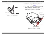
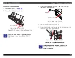
3. Remove the E-clip located just to the inside of the left hopper
release cam, as shown below.
Figure 4-25. E-Clip Removal
4. Slide the shaft to the left as far as it goes.
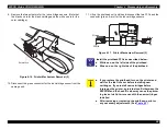
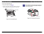
5. Remove the detection wheel by releasing the tab that secures it to
the left end of the shaft, as shown below.
Figure 4-26. Detection Wheel Removal
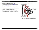
6. Slide the shaft all the way to the right. Then remove the E-clip
located between the right feed roller (loading or LD roller) and the
right side of the ASF frame.
7. Slide the shaft out of the ASF unit.
C H E C K
P O I N T
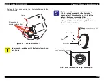
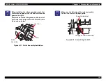
During assembly, you must orient both hopper release
cams so their notches face left as shown below. Also,
you must install them so they point in the same
direction as the flat part of the feed rollers as shown:
Figure 4-24. Hopper Release Cam Orientation
Notch faces to the left
when viewing ASF unit
front the front
Feed Roller (black rubber)
Cam (white
plastic)
E-Clip
ASF Roller Shaft
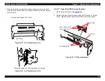
C H E C K
P O I N T
During assembly, make sure that the hole in the
detection wheel faces the same direction as the
hopper release cam.
F i x i n g T a b
D e t e c t i o n W h e e l
L D R o l l e r S h a f t
Roller Shaft
Summary of Contents for 900N
Page 1: ...EPSONStylusCOLOR900 900N Color ink jet printer TM SC900 N 6 59 0 18 ...
Page 8: ... 37 5 PRODUCTDESCRIPTION ...
Page 37: ... 37 5 OPERATINGPRINCIPLES ...
Page 67: ... 37 5 TROUBLESHOOTING ...
Page 89: ... 37 5 DISASSEMBLYANDASSEMBLY ...
Page 121: ... 37 5 ADJUSTMENTS ...
Page 156: ... 37 5 MAINTENANCE ...
Page 169: ... 37 5 APPENDIX ...
Page 179: ...EPSON Stylus COLOR 900 900N Chapter 7 Appendix 176 Figure 7 3 C265 Main Board Soldering side ...
Page 181: ...EPSON Stylus COLOR 900 900N Chapter 7 Appendix 178 Figure 7 6 C265 PNL Board ...
Page 195: ...06 03 01 02 for S E ASIA 03 03 05 03 04 EPSON STYLUS COLOR 900 No 7 10056 Rev 01 ...
Page 197: ......
Page 198: ......
Page 199: ......
Page 200: ......
Page 201: ......


