EPSON Stylus COLOR 900/900N
Chapter 2 Operating Principles
51
Mechanical Feedback
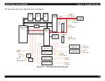
The block diagram below shows the support circuity for the sensors that
detect the status of the printer’s mechanical functions.
Figure 2-16. Printer Mechanism Sensor Support Circuitry
C N 9
2 0
2 1
C O B
C O C
+ 5
C N 8
2 1
2 0
L S 1
L S 2
E 0 5 B 5 9 ( I C 2 )
1 0 9
1 1 0
C O B
C O C
9 3
9 4
E N C B
E N C A
+ 5
E 0 5 B 6 0 ( I C 3 )
S W C 0
S W A 1
S W A 0
1 3 7
1 3 6
1 3 5
+ 5
+ 5
3 3
P S C
C N 1 5
H P
P E
A S F
1 6
1 5
1 4
4
C N 5
P S C
4
+ 5
Ink Cartridge Sensors
CR Home Position Sensor
Paper End Sensor
Power Control Signal (PSC)
Linear Encoder
ASF Sensor
Summary of Contents for 900N
Page 1: ...EPSONStylusCOLOR900 900N Color ink jet printer TM SC900 N 6 59 0 18 ...
Page 8: ... 37 5 PRODUCTDESCRIPTION ...
Page 37: ... 37 5 OPERATINGPRINCIPLES ...
Page 67: ... 37 5 TROUBLESHOOTING ...
Page 89: ... 37 5 DISASSEMBLYANDASSEMBLY ...
Page 121: ... 37 5 ADJUSTMENTS ...
Page 156: ... 37 5 MAINTENANCE ...
Page 169: ... 37 5 APPENDIX ...
Page 179: ...EPSON Stylus COLOR 900 900N Chapter 7 Appendix 176 Figure 7 3 C265 Main Board Soldering side ...
Page 181: ...EPSON Stylus COLOR 900 900N Chapter 7 Appendix 178 Figure 7 6 C265 PNL Board ...
Page 195: ...06 03 01 02 for S E ASIA 03 03 05 03 04 EPSON STYLUS COLOR 900 No 7 10056 Rev 01 ...
Page 197: ......
Page 198: ......
Page 199: ......
Page 200: ......
Page 201: ......


