EPSON Stylus COLOR 900/900N
Chapter 2 Operating Principles
49
2.3.4.2 Sensor Circuits
The printer’s sensors detect temperature and the mechanical status of
the printer. The CPU receives the temperature feedback, while two
ASICs receive the mechanical feedback: E05B59 (IC2) and E05B60
(IC3).
Temperature Feedback
The temperature feedback circuit includes three thermistors as well as
the temperature sensing circuitry in the nozzle selector inside the
printhead. Their functions are explained on the following page.
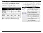
Figure 2-15. Temperature Sensor Support Circuitry
A N O D E 5
C N 8
C N 9
T h e r m i s t o r
N o z z l e
S e l e c t o r
4
H D 6 4 F 2 3 5 7 ( I C 1 )
T h e r m i s t o r o n t h e h e a t
s i n k o n t h e m a i n b o a r d
T h e r m i s t o r o n t h e m a i n b o a r d
A N 7
A N 6
A N 5
A N 4
A N 3
A N 2
A N 1
A N 0
1 1 2
1 1 1
1 1 0
1 0 9
1 0 8
1 0 7
1 0 6
1 0 5
1 9
2 1
2 0
1
2
9
1 0
H D S A M I
H P D S A M I
T H M
A N O D E 1
A N O D E 2
A N O D E 3
A N O D E 4
N o z z l e R o w s
R o w A
R o w C
R o w D
R o w E
R o w B
Summary of Contents for 900N
Page 1: ...EPSONStylusCOLOR900 900N Color ink jet printer TM SC900 N 6 59 0 18 ...
Page 8: ... 37 5 PRODUCTDESCRIPTION ...
Page 37: ... 37 5 OPERATINGPRINCIPLES ...
Page 67: ... 37 5 TROUBLESHOOTING ...
Page 89: ... 37 5 DISASSEMBLYANDASSEMBLY ...
Page 121: ... 37 5 ADJUSTMENTS ...
Page 156: ... 37 5 MAINTENANCE ...
Page 169: ... 37 5 APPENDIX ...
Page 179: ...EPSON Stylus COLOR 900 900N Chapter 7 Appendix 176 Figure 7 3 C265 Main Board Soldering side ...
Page 181: ...EPSON Stylus COLOR 900 900N Chapter 7 Appendix 178 Figure 7 6 C265 PNL Board ...
Page 195: ...06 03 01 02 for S E ASIA 03 03 05 03 04 EPSON STYLUS COLOR 900 No 7 10056 Rev 01 ...
Page 197: ......
Page 198: ......
Page 199: ......
Page 200: ......
Page 201: ......


