EPSON Stylus COLOR 900/900N
Chapter 2 Operating Principles
60
2.3.10 ASF Solenoid Driver Circuit
A solenoid switches the planetary gear train between the ASF and the
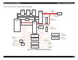
pumping mechanism. The figure below shows the solenoid driver circuit
block diagram.
Figure 2-23. ASF Solenoid Driver Circuit Block Diagram
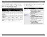
The output signal from IC2 and its effect on the solenoid are shown in
the table below:
Table 2-17. Conditions for Driving the ASF Solenoid
The solenoid’s specifcations are included below:
Table 2-18. ASF Solenoid Specifications
IC2 output (pin 83)
Solenoid’s operation
High (5 VDC)
On
Low (0 VDC)
Off
C N 1 6
G N D
2
1
V B B
+ 4 2
F 4
E 0 5 B 5 9 ( I C 2 )
A S F _ S O L
8 3
Q 9
Q 8
C o o l i n g f a n
Item
Specifications
Drive voltage
42 VDC
±
5%
Coil resistance
588
Ω
±
10% (at 20
°
C)
Induction
0.98 N (100 gf) or more
Summary of Contents for 900N
Page 1: ...EPSONStylusCOLOR900 900N Color ink jet printer TM SC900 N 6 59 0 18 ...
Page 8: ... 37 5 PRODUCTDESCRIPTION ...
Page 37: ... 37 5 OPERATINGPRINCIPLES ...
Page 67: ... 37 5 TROUBLESHOOTING ...
Page 89: ... 37 5 DISASSEMBLYANDASSEMBLY ...
Page 121: ... 37 5 ADJUSTMENTS ...
Page 156: ... 37 5 MAINTENANCE ...
Page 169: ... 37 5 APPENDIX ...
Page 179: ...EPSON Stylus COLOR 900 900N Chapter 7 Appendix 176 Figure 7 3 C265 Main Board Soldering side ...
Page 181: ...EPSON Stylus COLOR 900 900N Chapter 7 Appendix 178 Figure 7 6 C265 PNL Board ...
Page 195: ...06 03 01 02 for S E ASIA 03 03 05 03 04 EPSON STYLUS COLOR 900 No 7 10056 Rev 01 ...
Page 197: ......
Page 198: ......
Page 199: ......
Page 200: ......
Page 201: ......

