EPSON Stylus COLOR 900/900N
Chapter 4 Disassembly and Assembly
97
4.2.7 Power Supply Board Removal
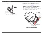
1. Remove the printer mechanism. (See
2. Disconnect connectors CN1, CN2, and CN3 from the C265 PSB/
PSE board.
3. Remove the three screws (including the one for grounding) that
secure the C265 PSB/PSE board to the lower case, and then
remove the C265 PSB/PSE board unit.
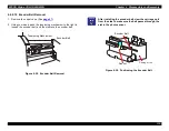
Figure 4-11. Removing the Connectors and Shield Box
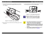
4. Remove the two screws securing the shield plate to the power
supply board, and then remove the shield plate.
Figure 4-12. Removing the Shield Plate
5. Remove the four screws
securing the C265 PSB/
PSE board to the bottom
frame, and then remove
the C265 PSB/PSE board.
.
Figure 4-13. C265 PSB/PSE Board Removal
Screws securing the C265 PSB/PSE Board
CN1 - CN3
Screws securing the Shield Plate
Screws securing the
C265 PSB/PSE Board
Summary of Contents for 900N
Page 1: ...EPSONStylusCOLOR900 900N Color ink jet printer TM SC900 N 6 59 0 18 ...
Page 8: ... 37 5 PRODUCTDESCRIPTION ...
Page 37: ... 37 5 OPERATINGPRINCIPLES ...
Page 67: ... 37 5 TROUBLESHOOTING ...
Page 89: ... 37 5 DISASSEMBLYANDASSEMBLY ...
Page 121: ... 37 5 ADJUSTMENTS ...
Page 156: ... 37 5 MAINTENANCE ...
Page 169: ... 37 5 APPENDIX ...
Page 179: ...EPSON Stylus COLOR 900 900N Chapter 7 Appendix 176 Figure 7 3 C265 Main Board Soldering side ...
Page 181: ...EPSON Stylus COLOR 900 900N Chapter 7 Appendix 178 Figure 7 6 C265 PNL Board ...
Page 195: ...06 03 01 02 for S E ASIA 03 03 05 03 04 EPSON STYLUS COLOR 900 No 7 10056 Rev 01 ...
Page 197: ......
Page 198: ......
Page 199: ......
Page 200: ......
Page 201: ......


