SMARC T335x Carrier Board Hardware Design Guide, Document Revision 1.2
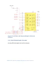
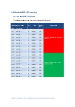
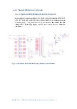
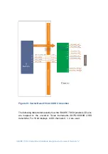
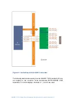
2.4 Parallel RGB LCD Interface
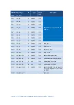
2.4.1. Parallel RGB LCD Signal
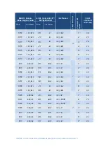
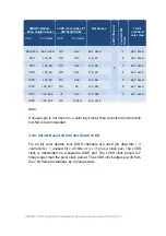
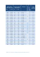
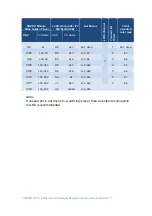
The following table shows the 24-bit parallel RGB signal.
SMARC Edge Finger
I/O
Type
Power
Rail
Description
Pin#
Pin
Name
S111
LCD_D16
O
CMOS
3.3V
Red LCD data signals (LSB: D16,
MSB: D23)
S112
LCD_D17
O
CMOS
3.3V
S113
LCD_D18
O
CMOS
3.3V
S114
LCD_D19
O
CMOS
3.3V
S115
LCD_D20
O
CMOS
3.3V
S116
LCD_D21
O
CMOS
3.3V
S117
LCD_D22
O
CMOS
3.3V
S118
LCD_D23
O
CMOS
3.3V
S102
LCD_D8
O
CMOS
3.3V
Green LCD data signals (LSB:
D8, MSB: D15)
S103
LCD_D9
O
CMOS
3.3V
S104
LCD_D10
O
CMOS
3.3V
S105
LCD_D11
O
CMOS
3.3V
S106
LCD_D12
O
CMOS
3.3V
S107
LCD_D13
O
CMOS
3.3V
S108
LCD_D14
O
CMOS
3.3V
S109
LCD_D15
O
CMOS
3.3V