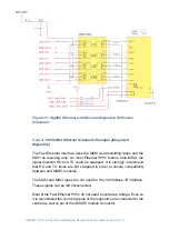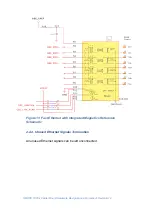
SMARC T335x Carrier Board Hardware Design Guide, Document Revision 1.2
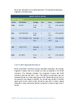
Above are magnetics for normal temperature. For industrial temperature
magnetics are listed below.
SMARC T335X-I (LAN8720i)
Qualified Magnetics
Vendor
Part Number
Package
Core
Temp
Configuration
Pulse
HX1188
16-pin
SOIC
4
-40
o
~85
o
C
HP Auto-MDIX
Halo
TG110-RPE5N5
16-pin
SOIC
4
-40
o
~85
o
C
HP Auto-MDIX
Halo
HFJ11-RPE26E-L12RL
Integrated
RJ45
4
-40
o
~85
o
C
HP Auto-MDIX
POE
TDK
TLA-6T717W
Integrated
RJ45
4
-40
o
~85
o
C
HP Auto-MDIX
Delta
LFE-8505T
16-pin
SOIC
4
-40
o
~85
o
C
HP Auto-MDIX
2.2.2.3. LAN Component Placement
When using RJ45 connectors without integrated magnetics, the discrete
magnetics module has to be placed as close as possible to the RJ45
connector. The distance between the magnetics module and RJ45
connector must be less than 1 inch. This distance requirement must be
observed during the carrier board layout when implementing
LAN
. Due to
the insertion loss budget of
SMARC
, the overall trace length of the
MDI
signal pairs on the carrier board should be less than 4 inches. Signal
attenuation could cause data transfer problems for traces longer than 4
inches.

