SMARC T335x Carrier Board Hardware Design Guide, Document Revision 1.2
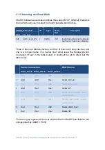
2.11 Selecting the Boot Mode
SMARC
hardware specification defines three pins (
BOOT_SEL[0:2]
) that allow
the Carrier board user to select from eight possible boot devices.
SMARC Edge Finger
I/O
Type
Power
Rail
Description
Pin#
Pin
Name
S48
BOOT_SEL[0:2]#
I
CMOS
3.3V
Input straps determine the Module
boot device. Pulled up on Module.
Three of them are Module devices, and four of them are Carrier devices, and
one is a remote device. The Carrier shall either leave the Module pin Not
Connected (“Float” in the table below) or shall pull the pin to GND, per the
table below.
Carrier Connection
BOOT_SEL2# BOOT_SEL1# BOOT_SEL0#
Boot Source
0
GND
GND
GND
Carrier SATA
1
GND
GND
Float
Carrier SD Card
2
GND
Float
GND
Carrier eMMC Flash
3
GND
Float
Float
Carrier SPI
4
Float
GND
GND
Module device (NAND, NOR) -
vendor specific
5
Float
GND
Float
Remote boot (GBE, serial) -
vendor specific
6
Float
Float
GND
Module eMMC Flash
7
Float
Float
Float
Module SPI
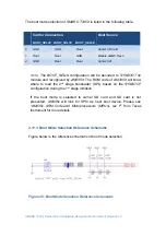
The text in grey represents the boot mode defined in
SMARC
specification, but
not supported by
SMARC T335X
.


