
SMARC T335x Carrier Board Hardware Design Guide, Document Revision 1.2
2.10.2. I2C Interface Implementation Guidelines
2.10.2.1. Terminations
I2C_PM
bus has a 2.2k pull-up to 1.8V on module.
I2C_GP
and
I2C_LCD
buses have a 2.2k pull-up to 3.3V on module. There is no need to pull up
on carrier.
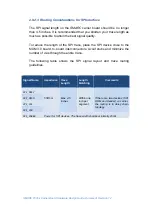
2.10.2.2. Routing Considerations for I2C Interface
The I2C does not need to be routed as differential pair, but it is
recommended not to separate the data and clock lines too much. It is not
required to route the bus as daisy chain as the stub length is not a
problem. The maximum trace length is limited due to the capacitive load of
the traces.
Therefore, traces should be kept short as possible by using a star topology.
See
SMARC T335X
layout guide for trace routing guidelines and the
SMARC
specification for more information about this subject.
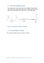
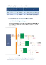
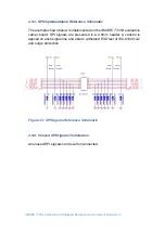
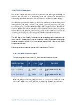
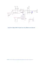
2.10.3. I2C Implementation Reference Schematic
In
SMART-BEE
evaluation carrier,
I2C_PM
bus is also connected to a
TI
TLV320AIC3106
audio codec and an On Semiconductor
AT24
4KB
EEPROM that can access the carrier board information. The schematic for
audio part can be found at I2S section of this document. The example shown
below is implemented of I2C EEPROM on the
SMARC T335X
evaluation
carrier board.
I2C_PM
is level shifted to 3.3V on carrier from 1.8V on
module.


