SMARC T335x Carrier Board Hardware Design Guide, Document Revision 1.2
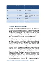
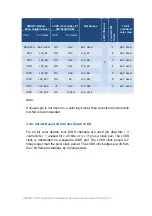
Signal
Pin
IO
Description
VCC
1
P5V
+5V Power Supply
DATA
‐
2
I/O USB
Universal Serial Bus Data, negative
differential signal.
DATA+
3
I/O USB
Universal Serial Bus Data, positive
differential signal.
GND
4
P
Ground
GNDSHLD
5
P
Shield Ground
GNDSHLD
6
P
Shield Ground
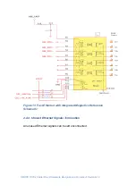
2.3.3.2. USB Client Reference Schematic
The
USB0_OTG_ID
signal is used to detect which type of USB connector
is plugged into the OTG jack (Mini-AB jack). When a Mini-A connector is
inserted, the ID pin is connected to signal ground, causing the OTG port to
be configured as a host. If a Mini-B USB connector is inserted, the ID pin
is left unbiased and the OTG port will be configured as a slave device.
Usually, there is a 10k pull-up to 3.3V on module for the
USB0_OTG_ID
signal, but TI Sitara AM335x does not require pull-ups on module.
The
USB0_VBUS
input signal is only used if the
OTG
port is in client
mode (Mini-B USB connector plugged in or by software configured as
slave only). The signal is used to detect whether a host is connected on
the other end of the USB cable. This signal is 5V tolerant and can be
connected directly to the power supply pin of the USB jack.
ESD
protection diodes should be used for this signal.
The
USB0_EN_OC#
signal is only used when the OTG port is operating in
host mode (Mini-A USB connector is plugged in or the port is configured
by software as host only).
SMARC
combines
USB0_EN
and
USB0_OC#
signals as a single
USB0_EN_OC#
signal. The
USB0_EN
signal is used
to enable the USB bus power supply if it needs to be switchable. A USB
compliant design needs to detect over current on the USB bus power
supply and switch the power off should an over-current condition occur.
The
USB0_OC#
signal is used to signal to the host controller that an
over-current condition has occurred. Usually, this signal is active low has a
10k pull-up resistor to 3.3V on module, but TI Sitara AM335x does not

