SMARC T335x Carrier Board Hardware Design Guide, Document Revision 1.2
MXM3 standard gangs large groups of pins together to provide ~80W
capable power paths needed for X86 graphics cards. The SMARC
module “ungangs” these pins to allow more signal pins. Footprint and
pin numbering information for application of this 314 pin connector to
SMARC is given in the sections below.
4.2 Module and Carrier Connector Pin Numbering Convention
The Module pins are designated as
P1 - P156
on the Module Primary (Top)
side, and
S1 – S158
on the Module Secondary (Bottom) side. There is a total
of 314 pins on the Module. The connector is sometimes identified as a 321 pin
connector, but 7 pins are lost to the key (4 on the primary side and 3 on
secondary side).
The SMARC Module pins are deliberately numbered as
P1 - P156
and
S1 -
S158
for clarity and to differentiate the SMARC Module from MXM3 graphics
modules, which use the same connector but use the pins for very different
functions. MXM3 cards and MXM3 baseboard connectors use different pin
numbering scheme.
4.3 Module Outline – 82mm x 50mm Module
Two Module sizes are defined in
SMARC
specification: 82mm x 50mm and
82mm x 80mm. Since
SMARC T335X
is an 82mm x 50mm module, we will
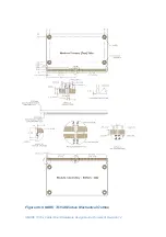
only draw our attention on this dimension. The figure on the following page
details the 82mm x 50mm Module mechanical attributes, including the pin
numbering and edge finger pattern.

